PCBRM_User_Manual_R9.pdf - 第65页
PCBRM15 & PCBRM System 5. 2 User’s Manual Chapter 4: Process es & Appl icati ons Part No. 4005.00.906 4- 23 • It may be d esired to turn on solder flow while board is in the preheat position to a llow flow well t…
PCBRM15 & PCBRM System 5.2 User’s Manual
Chapter 4: Processes & Applications
Part No. 4005.00.906 4-22
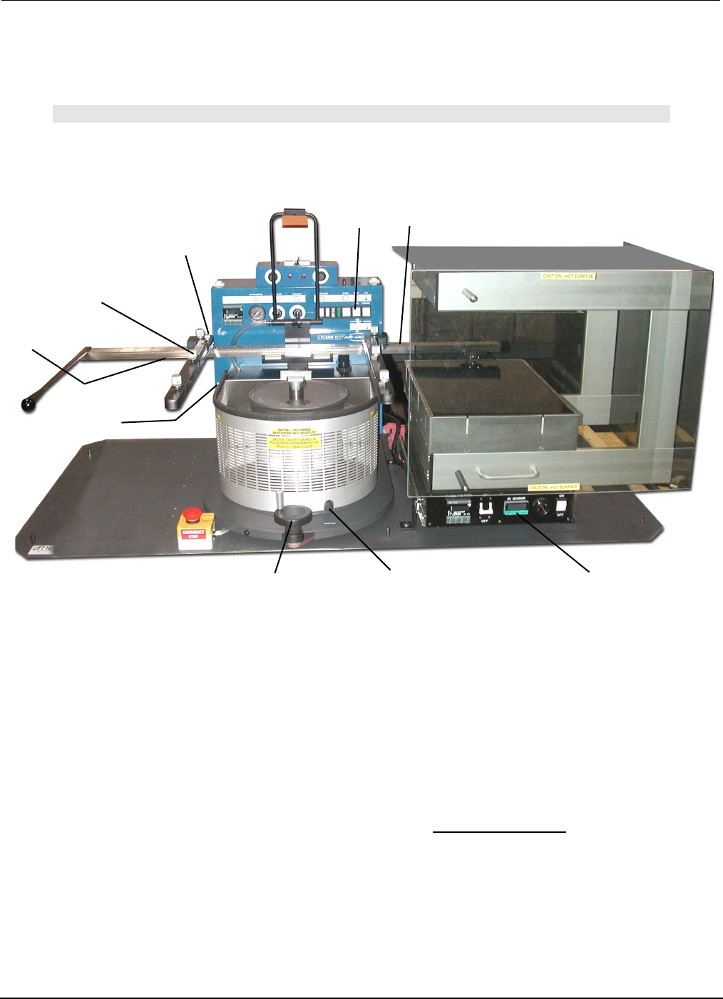
Y-Axis Lock
Preheater
Z-Axis Lock
Board Lock
X-Axis
Carrier Lock
Z-Axis
Adjustment Wheel
X-Axis Lock
(preheater)
Board Temperature
Display
X-Axis Lock
(solder pot)
Mode Switch
(manual)
4.13 PCBRM System 5.2 - Soldering Sequence: Using Manual Mode for
Soldering
Note
SET SOLDER CYCLE DURATION CONTROL TO MAXIMUM SETTING. FLOW MUST BE
DETERMINED PRIOR TO THESE STEPS.
1. Install flow well.
2. Load board into carrier. If y-axis lock is used, position board to edge and tighten. Tighten board locks.
3. Slide board into preheater using the carrier handle until the x-axis lock (preheater) is reached. Adjust
z-axis adjustment when necessary. Be sure carrier is in the top position to avoid hitting flow well.
Carrier may be lowered to enhance preheating. Allow board to preheat to desired topside
temperature. IR sensor will monitor and display board temperature.
4. When board has reached desired temperature (alarm will occur) press footswitch to activate solder
flow. Skim off dross, if necessary.
5. Slide board over solder wave, using the carrier handle—until carrier hits x-axis lock. Turn carrier lock
to set.
6. Turn Z-Axis Adjustment Wheel until carrier hits z-axis lock (System 5.2 only).
7. Allow sufficient time for reflow.
8. Slowly turn Z-Axis Adjustment Wheel moving board upward to allow solder to slowly peel from the
component leads to alleviate bridging.
9. Turn off solder flow by pressing right side of footswitch.
10. Turn Z-Axis Adjustment Wheel to top position. Loosen Carrier Lock. Slide board away from solder
pot using the carrier handle. Remove board.
11. Repeat process.
Process Notes:

PCBRM15 & PCBRM System 5.2 User’s Manual
Chapter 4: Processes & Applications
Part No. 4005.00.906 4-23
• It may be desired to turn on solder flow while board is in the preheat position to allow flow well to
heat soak and dross to be skimmed prior to soldering.
• Reduce bridging by adjusting Ramp Down Flow Rate to zero (0). Or, manually raise board slowly
with Z-Axis Adjustment Wheel while solder is still flowing.
• Flux entire lead area. It may be required to flux topside of board. Allow sufficient temperature to a
be achieved to activate flux.
• Board must be level to solder wave. Fixturing may be required.
• The vertical position of the board is critical for proper soldering results. Allow solder to contact all
leads, but sufficient clearance for solder to flow. Bridging may be reduced by raising carrier position
and allowing solder to wick up the leads.
• Using tacky flux may allow more flux to remain during reflow, reducing bridging.
• Increasing preheat may be required for thermal challenging and lead free assemblies.
• It may be desired to lower the process temperature and increase process time if the board is prone
to delamination and/or discoloring.

PCBRM15 & PCBRM System 5.2 User’s Manual
Chapter 4: Processes & Applications
Part No. 4005.00.906 4-24
4.14 Removal Procedure
4.14.1 Set Up
• Set Ramp Down Flow Rate to 10.
• Set Air Regulator to 5-7 psi.
• Follow same procedure for automatic soldering procedure. If manual soldering procedure is used,
the operator must press the footswitch to stop the solder pumping and activate the hole cleaning
system.
4.14.2 Operation
Use automatic or manual procedure as described in soldering section up the when solder is contacting
the board.
Allow sufficient time for solder to contact component leads for easy removal.
Observe component leads and when all leads are molten, lift the component from the board using an
extractor tool that firmly grasps the component body. If solder is still flowing, interrupt cycle by pressing
the right side of the footswitch. Component should lift out easily.
The hole cleaning operation starts immediately at the end of the component removal procedure. There
will be an audible signal that indicates solder has stopped flowing against the board. At this time, lower
the Air Cleaning Hood. It is important that sufficient downward pressure be applied to insure a good
seal between the hood and board surface. Be sure entire area is sealed. Air leakage will prevent
maximum effectiveness of system. Hold is place during the entire time the air is applied.
Low pressure air comes on automatically 1 ½ seconds after the solder stops flowing, forcing the
molten solder to drop from the holes into the empty flow well. The 1 ½ seconds delay prevents
pressurized air from coming in contact with the flowing solder.
The bottom of the board may have bridging or icicling caused by the moving air. The next operation of
resoldering of the replacement component will eliminate these conditions.
Depending upon the heat sink characteristics of the board, the number of leads, and shape of the lead
pattern, there will be some holes that will not be completely clear of solder.