PCBRM_User_Manual_R9.pdf - 第19页
PCBRM15 & PCBRM System 5.2 User’s Manual Chapter 2: Requirements/Machine Overview Part No. 4005.00.906 2-5 (L) (M) (K) (C) (E) (F) (G) (I) (J) (B) (A) (Q) (P) (R) (O) (N)- option (Q) (H) (D) 2.4 PCBRM15 and System 5.…
PCBRM15 & PCBRM System 5.2 User’s Manual Chapter 2: Requirements/Machine Overview
Part No. 4005.00.906 2-4
(I) - option
(J)
(C)
(D)
(A)
(H) - option
(B)
(F)
(G)
(B)
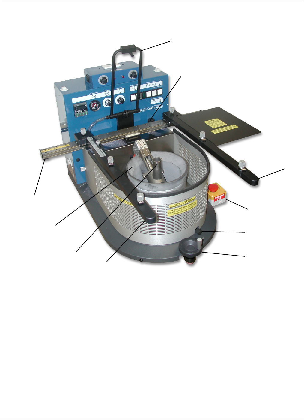
2.3 PCBRM15 - Module Overview
(A) X-Axis Carrier Rail - Cantilever carrier rail adjusts to hold PCB up to 22”W.
(B) PCB Carrier Arms - Carrier arms hold PCB up to 21” deep. PCB Stops with reference scale
provides one time set-up of repetitive assemblies.
(C) X-Axis Carrier Lock - Once PCB is aligned over flow well, the carrier is locked in place.
(D) Z-Axis Height Adjustment - Adjusts height of PCB in relation to the flow well.
(F) Solder Pot
(G) Solder Pump
(H) APS System- Blows low pressure air through holes in PCB of removed component to clear them of
solder.
(I) APS System Air Regulator – Sets air pressure.
(J) Emergency Stop – Shuts system down immediately if required.
PCBRM15 & PCBRM System 5.2 User’s Manual Chapter 2: Requirements/Machine Overview
Part No. 4005.00.906 2-5
(L)
(M)
(K)
(C)
(E)
(F)
(G)
(I)
(J)
(B)
(A)
(Q)
(P)
(R)
(O)
(N)- option
(Q)
(H)
(D)
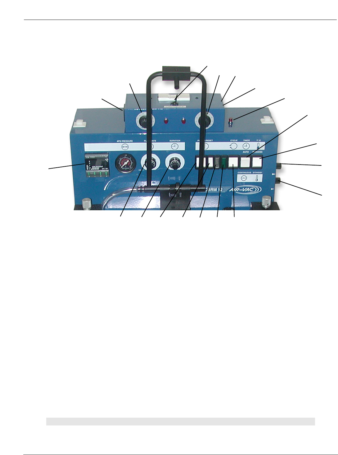
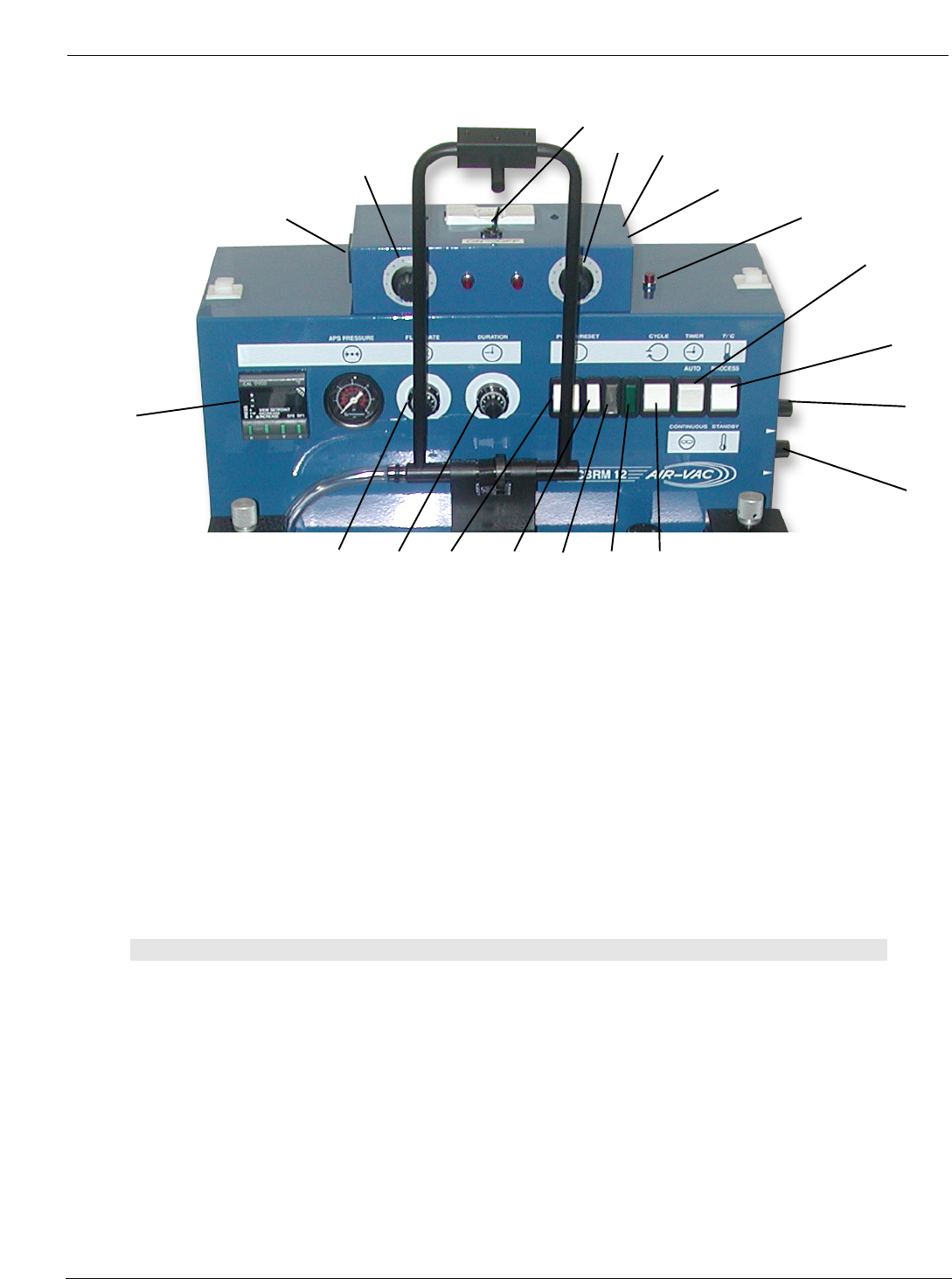
2.4 PCBRM15 and System 5.2 - Control Panel Overview
(A) Digital Temperature Controller - Microprocessor provides two programmable set points: Process
Temperature and Standby/Interlock Temperature. Digital readout of actual temperature is accurate
within +/-1% of full scale. (Thermocouple is located at bottom of solder pot).
(B) Solder Flow Rate Control – Process flow rate can be varied and controlled during the duration
cycle. There are three Solder Flow Rate Controls: Ramp Up, Process, and Ramp Down. The Flow Rate
Control adjusts the pumping speed of the solder to produce a level flowing wave through the Flow Well.
Too low of speed will not pump the solder against the pcb contacting all the component leads. Too high
a setting will cause solder to flood the board surface.
(C) Solder Duration Control – The length of the time solder flows in one cycle can be set. The
process cycle can be started by either depressing the START ON the Footswitch or pressing the
CYCLE Start-switch.
• (D) Mode Switch - Automatic Mode – With the Timer Switch in the Automatic Mode, specific
timing logic is available up to 60 seconds and is adjusted and set by the Duration Control. The
settings between 1 and 5 give the range used for most applications. If the cycle needs to be
interrupted, pressing the STOP ON of the Footswitch will stop the cycle.
• (D) Mode Switch - Continuous Mode – With the Mode Switch in Continuous, the Duration
Control Logic and Cycle Start Switch are now by-passed. Solder will flow until the STOP pedal
is depressed. Solder flow will not resume until the STOP pedal is released. The Continuous
Mode is operator controlled.
Note:
THE CENTER POSITION OF THE MODE SWITCH (D) IS “OFF”.
PCBRM15 & PCBRM System 5.2 User’s Manual Chapter 2: Requirements/Machine Overview
Part No. 4005.00.906 2-6
(L)
(M)
(K)
(C)
(E)
(F)
(G)
(I)
(J)
(B)
(A)
(Q)
(P)
(R)
(O)
(N)- option
(Q)
(H)
(D)
(E) Main Power Switch – ON/OFF provides electrical power to the systems.
(F) Relatch Switch – Resets Main Power after unit is turned off or Emergency stopped.
(G) White Light – Indicates Main Power is on.
(H) Transformer Breakdown Light – Indicates failure of transformer coil isolation.
(I) Green Light – Indicates solder is molten and the machine is ready to cycle.
(J) Cycle Switch – Activates the Cycle Duration with Mode Switch in Automatic Mode.
(K) Temperature Controller – Controls temperature of solder.
(L) Ramp Up Flow Rate - Adjusts motor start speed of the pump, either quickly or slowly. To increase
ramp time, turn knob counter-clockwise. To decrease, turn clockwise.
(M) Ramp Down Flow Rate - Adjusts motor stop speed of the pump, either quickly or slowly. This can
help to produce a better solder joint. To increase ramp time, turn the knob counter-clockwise, to
decrease turn clockwise.
Note:
FLOW RATE INFLUENCES THE TOTAL DURATION/PROCESS CYCLE. RAMP DOWN FLOW RATE
INFLUENCES THE TIME WHEN THE AIR IS ACTIVATED FOR THE AIR CLEANING SYSTEM (APS
OPTION). FOR SOLDERING, SET RAMP DOWN TO "0". FOR DESOLDERING, SET TO "10".
(N) Flow Well Heater Box (option) – When external heaters are required for heating large flow wells.
(O) Heater Control Right (high/low) – Adjusts right flow well heater from low to high temp.
(P) Heater Control Left (high/low) – Adjusts left flow well heater from low to high temp.
(Q) Left & Right Plugs – Plug heater for flow wells here.
(R) ON/OFF Switch