PCBRM_User_Manual_R9.pdf - 第34页
PCBRM15 & PCBRM System 5.2 User’s Manual Chapter 3: Set Up & Installation Part No. 4005.00.906 3-8 Compliant Arm Lock Temperature Monitor Activation Switch Solder Baffle Compliant Arm Lock Knobs Y-Axis Stop and S…
PCBRM15 & PCBRM System 5.2 User’s Manual Chapter 3: Set Up & Installation
Part No. 4005.00.906 3-7
Compliant
(carrier) Arm
Lock Assembly
Carrier Arm
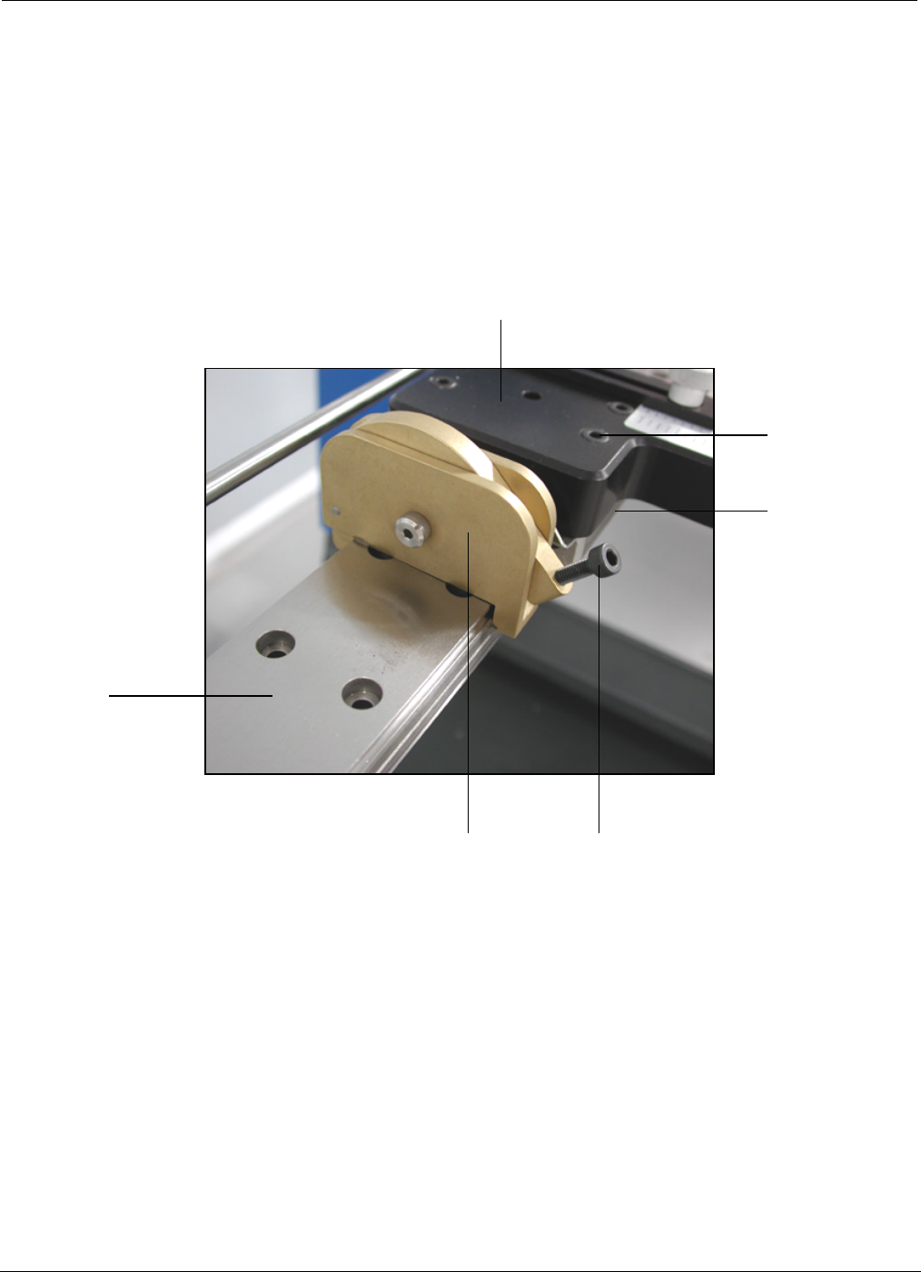
3.3 PCBRM System 5.2 - Carrier Arms Installation
• Loosen lock knob so compliant (carrier) arm lock assembly can straddle the x-axis rail.
• Place compliant arm lock assembly in place, as shown.
• Use mounting screws to mount carrier arm to bearing block.
Lock Knob
Bearing
Block
Mounting
Screw
X-Axis
Rail
PCBRM15 & PCBRM System 5.2 User’s Manual Chapter 3: Set Up & Installation
Part No. 4005.00.906 3-8
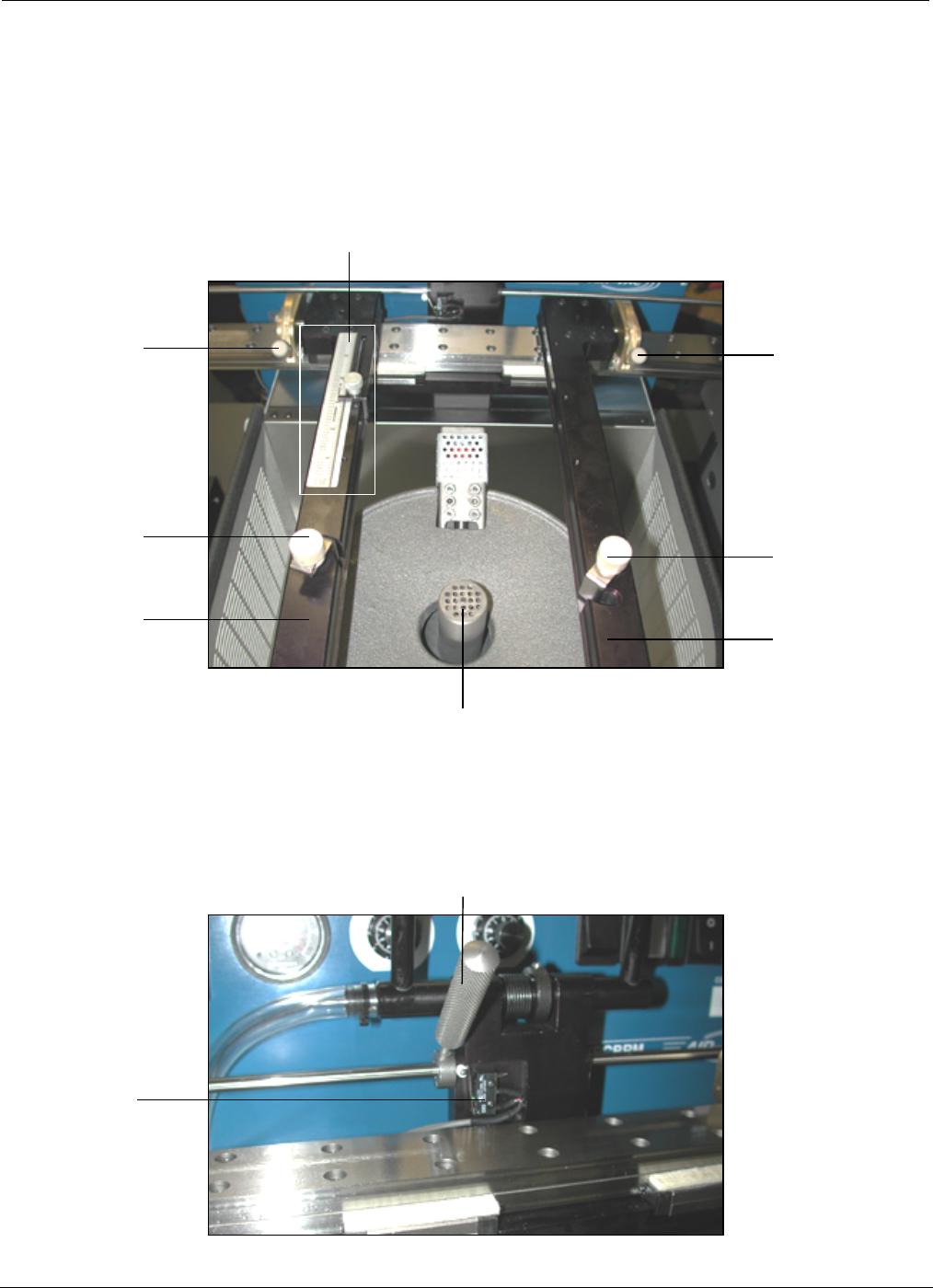
Compliant Arm Lock
Temperature
Monitor
Activation
Switch
Solder Baffle
Compliant
Arm Lock
Knobs
Y-Axis Stop and Scale
Compliant
Arm Lock
Knobs
Board
Lock Knobs
Carrier
Arms
Board
Lock Knobs
Carrier
Arms
3.4 PCBRM System 5.2 – X Axis Stops, Set Up, Function
• Locate PCB in carrier arms and lock arms in place using compliant arm lock knobs.
• Locate PCB in the y-axis and set stop.
• Lock PCB in arms using board lock knobs.
• Set x-axis stop (preheater) once PCB has been located in the preheater.
PCBRM15 & PCBRM System 5.2 User’s Manual Chapter 3: Set Up & Installation
Part No. 4005.00.906 3-9
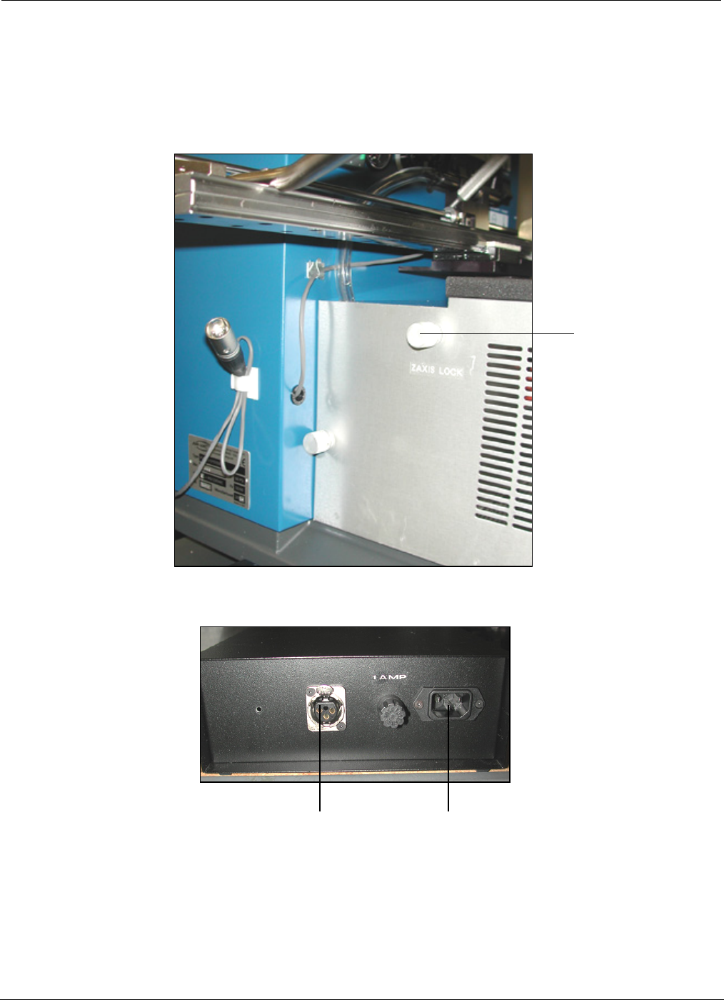
Z-Axis Lock
3.5 PCBRM System 5.2 – Z Axis Stop, Set Up, Function
• The z-axis lock presets a repeatable stop in the Z-Axis for board solder location.
Power
Receptical
Microswitch
Interface
Receptical