PCBRM_User_Manual_R9.pdf - 第30页
PCBRM15 & PCBRM System 5.2 User’s Manual Chapter 3: Set Up & Installation Part No. 4005.00.906 3-4 3.2 PCBRM15 – Carrier Arms Installation • Install right and left carrier arms to the bearing block using the M4 s…
PCBRM15 & PCBRM System 5.2 User’s Manual Chapter 3: Set Up & Installation
Part No. 4005.00.906 3-3
3 Set Up & Installation
3.1 Leveling Module
CAUTION:
OPERATION OF THIS MODULE INVOLVES PUMPING OF MOLTEN SOLDER. ALL NORMAL SAFETY
PRACTICES SHOULD BE OBSERVED WITH SPECIAL ATTENTION TO THE FOLLOWING:
SAFETY GLASSES SHOULD BE WORN AT ALL TIMES.
DO NOT MOVE MODULE WHILE SOLDER IS MOLTEN.
DISCONNECT POWER BEFORE SERVICING MODULES.
CAUTION:
LEVELING OF MODULE SHOULD NOT BE ATTEMPTED WITH MOLTEN SOLDER IN THE POT.
Note:
LEVELING IS CRITICAL TO PROVIDE CORRECT SOLDER FLOW.
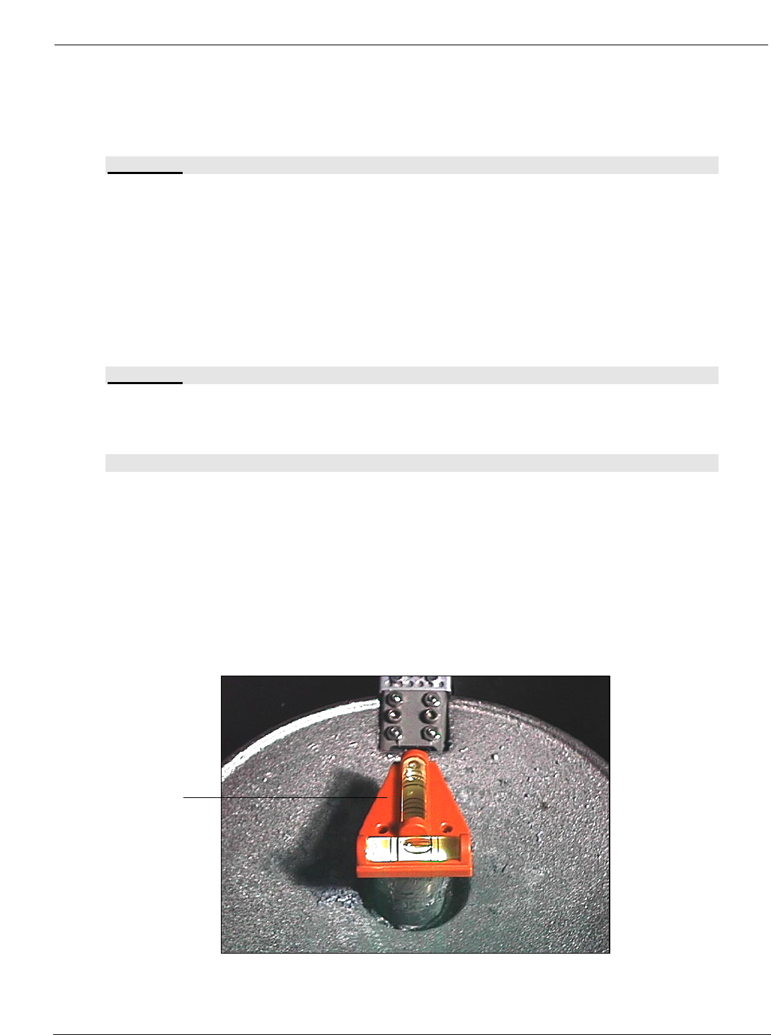
• Level machine on table.
• Place the level (supplied with tool kit) on Pump Housing (A). Level machine (front to back and
side to side) by adjusting the Leveling Legs.
• After leveling is completed, lock legs with jam nuts.
(A)
PCBRM15 & PCBRM System 5.2 User’s Manual Chapter 3: Set Up & Installation
Part No. 4005.00.906 3-4
3.2 PCBRM15 – Carrier Arms Installation
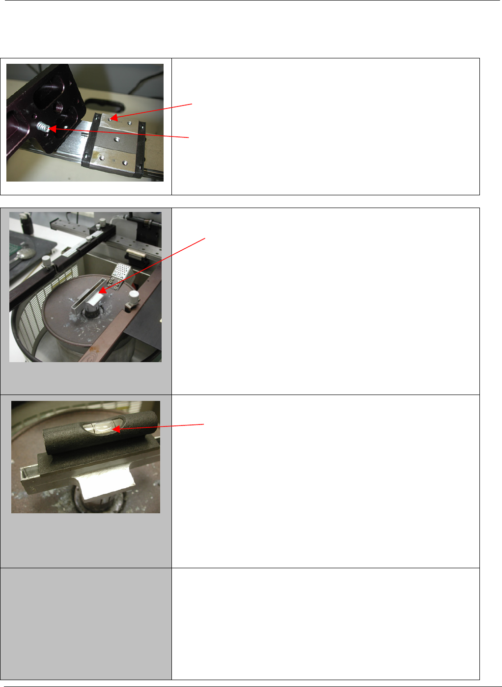
• Install right and left carrier arms to the bearing block
using the M4 screws supplied.
• When installing the arms, please note that the spring
must be installed as shown.
1. Start with a flow well installed on the solder pump.
2. Place a level on the flow well and note level of the
well.
PCBRM15 & PCBRM System 5.2 User’s Manual Chapter 3: Set Up & Installation
Part No. 4005.00.906 3-5
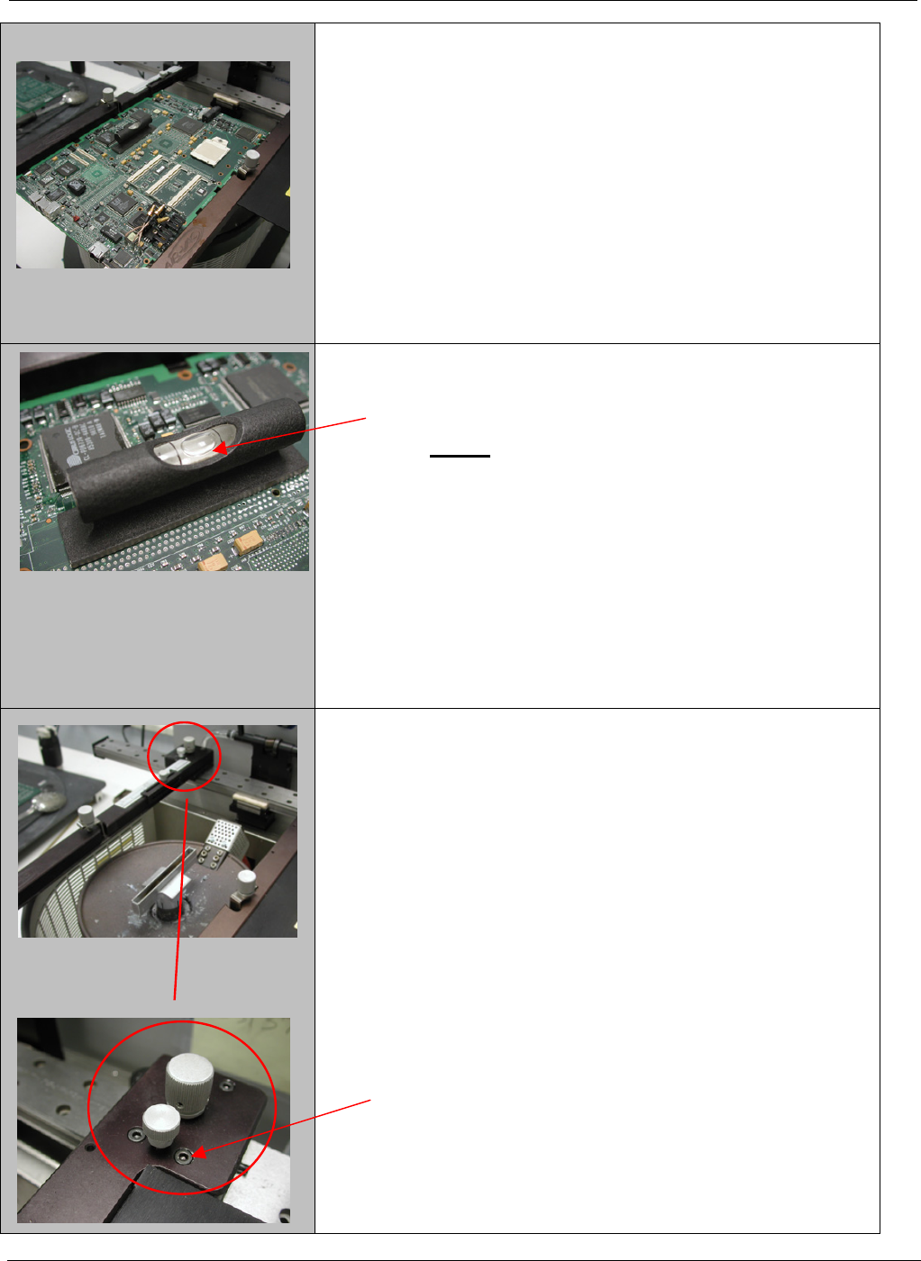
3. Place the board to be used in the process in to the
carrier arms. Align the site to be processed on the
board over the flow well and lock in place.
4. The board now will need to be leveled to match the
flow well. (step 2)
NOTE: The adjustment will be in the Y-axis only
not the X-axis
5. To adjust the board to match the flow well, loosen
the two front screws only on each arm two turns.