PCBRM_User_Manual_R9.pdf - 第45页
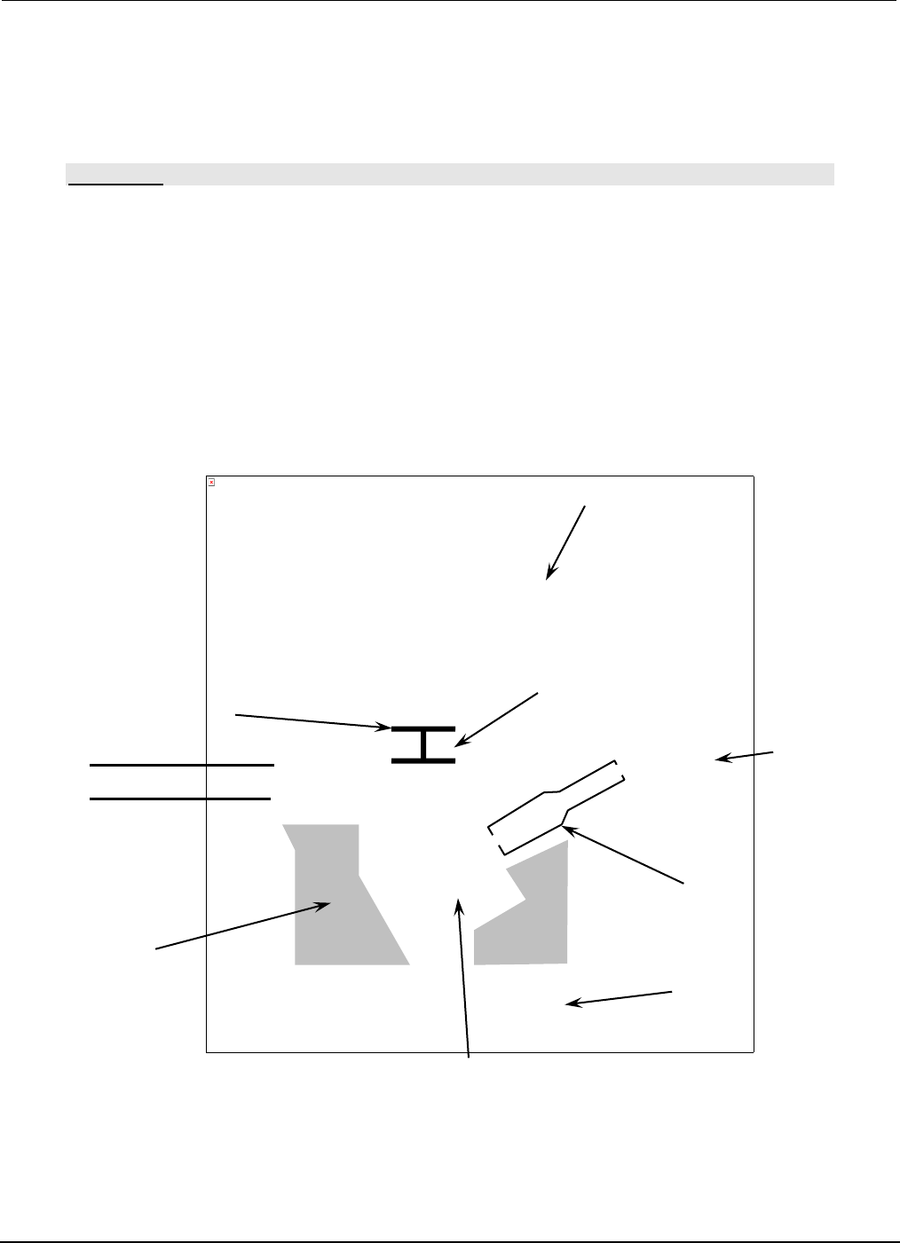
PCBRM15 & PCBRM System 5. 2 User’s Manual Chapter 4: Process es & Appl icati ons Part No. 4005.00.906 4-3 A (B) Solder Pot Pump Solder 1/2” Solder Level Pump Housing Pump Sleeve Impeller The picture can't be…

PCBRM15 & PCBRM System 5.2 User’s Manual
Chapter 4: Processes & Applications
Part No. 4005.00.906 4-2
PCBRM15 & PCBRM System 5.2 User’s Manual
Chapter 4: Processes & Applications
Part No. 4005.00.906 4-3
A
(B)
Solder Pot
Pump
Solder
1/2”
Solder
Level
Pump Housing
Pump Sleeve
Impeller
The picture can't be displayed.
4 Processes & Applications
4.1 Adding Solder
CAUTION:
USE INSULATED GLOVES WHEN WORKING AROUND HEATED AREA. BE CERTAIN THE MODE
SWITCH IS IN THE OFF POSITION (NEUTRAL POSITION.)
• Remove Pot Cover (A).
• Insert Baffle Assembly (B) into Pump.
• Power up system by depressing main power and reset switch on the PCBRM module.
• When the pot reaches 500°F (260°C), place solder bars into pot until solder level is reached.
• Using gloves provided, place pot cover back on pot once solder has melted.
• Power up preheater panels (for PCBRM Systems only).
PCBRM15 & PCBRM System 5.2 User’s Manual
Chapter 4: Processes & Applications
Part No. 4005.00.906 4-4
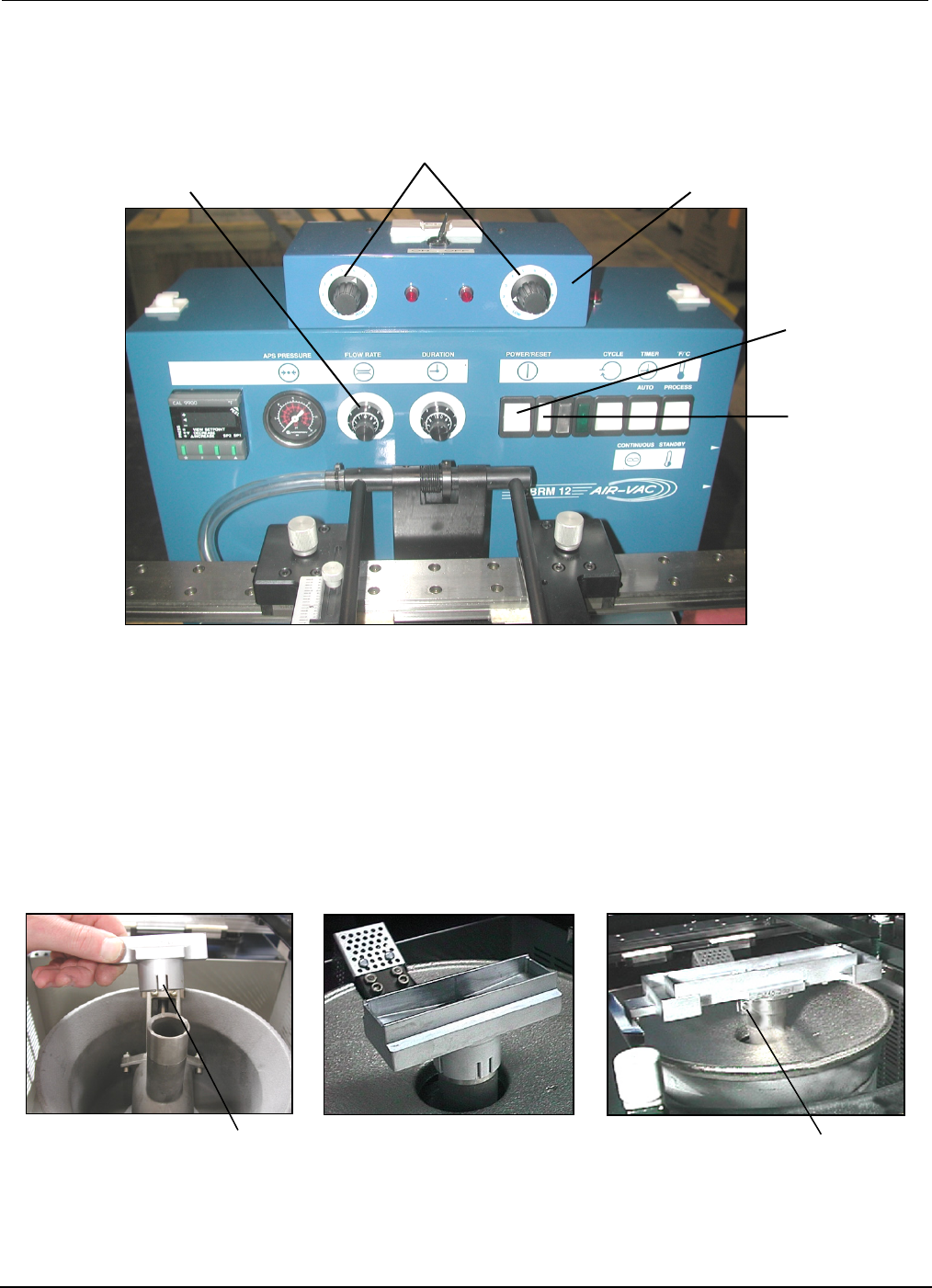
Main Power
Reset Switch
Solder Flow Rate Control
Hi/Low Flow Well Heater Adjust
Flow Well Heater Box
Spring Tabs
Screw
1
2
3
4.2 Flow Well Set-Up
• Push the Main Power and Reset Switches. Process temperature is factory set at 500˚F (adjust as
required).
• Using insulated gloves, push down on flow well and insure it is completely seated on pump. If
required, adjust Spring Tabs of well or tighten Clampable Shank (screw) as required to insure flow
well maintains firmly positioned on pump.