PCBRM_User_Manual_R9.pdf - 第44页
PCBRM15 & PCBRM System 5. 2 User’s Manual Chapter 4: Process es & Appl icati ons Part No. 4005.00.906 4-2

PCBRM15 & PCBRM System 5.2 User’s Manual
Chapter 4: Processes & Applications
Part No. 4005.00.906 4-1
4: Processes & Applications
4 Processes & Applications ................................................................................................................... 3
4.1 Adding Solder ............................................................................................................................................ 3
4.2 Flow Well Set-Up ...................................................................................................................................... 4
4.3 Cleaning Hood Set Up (option) ................................................................................................................ 7
4.4 Solder Temperature .................................................................................................................................. 8
4.5 PCB Hole Cleaning Procedure ................................................................................................................ 9
4.6 Soldering Replacement Component ........................................................................................................ 9
4.7 Specific Production Soldering Applications ........................................................................................... 9
4.8 Temperature Controller (Watlow) ........................................................................................................ 10
4.9 Temperature Controller (CAL 9900) .................................................................................................... 11
4.10 Operator Procedures .............................................................................................................................. 12
4.11 Set-Up and Process a PCB (step by step) .............................................................................................. 13
4.12 PCBRM System 5.2 - Soldering Sequence: Using Auto Mode for Soldering .................................... 21
4.13 PCBRM System 5.2 - Soldering Sequence: Using Manual Mode for Soldering ............................... 22
4.14 Removal Procedure ................................................................................................................................ 24
4.15 Component Replacement ....................................................................................................................... 25

PCBRM15 & PCBRM System 5.2 User’s Manual
Chapter 4: Processes & Applications
Part No. 4005.00.906 4-2
PCBRM15 & PCBRM System 5.2 User’s Manual
Chapter 4: Processes & Applications
Part No. 4005.00.906 4-3
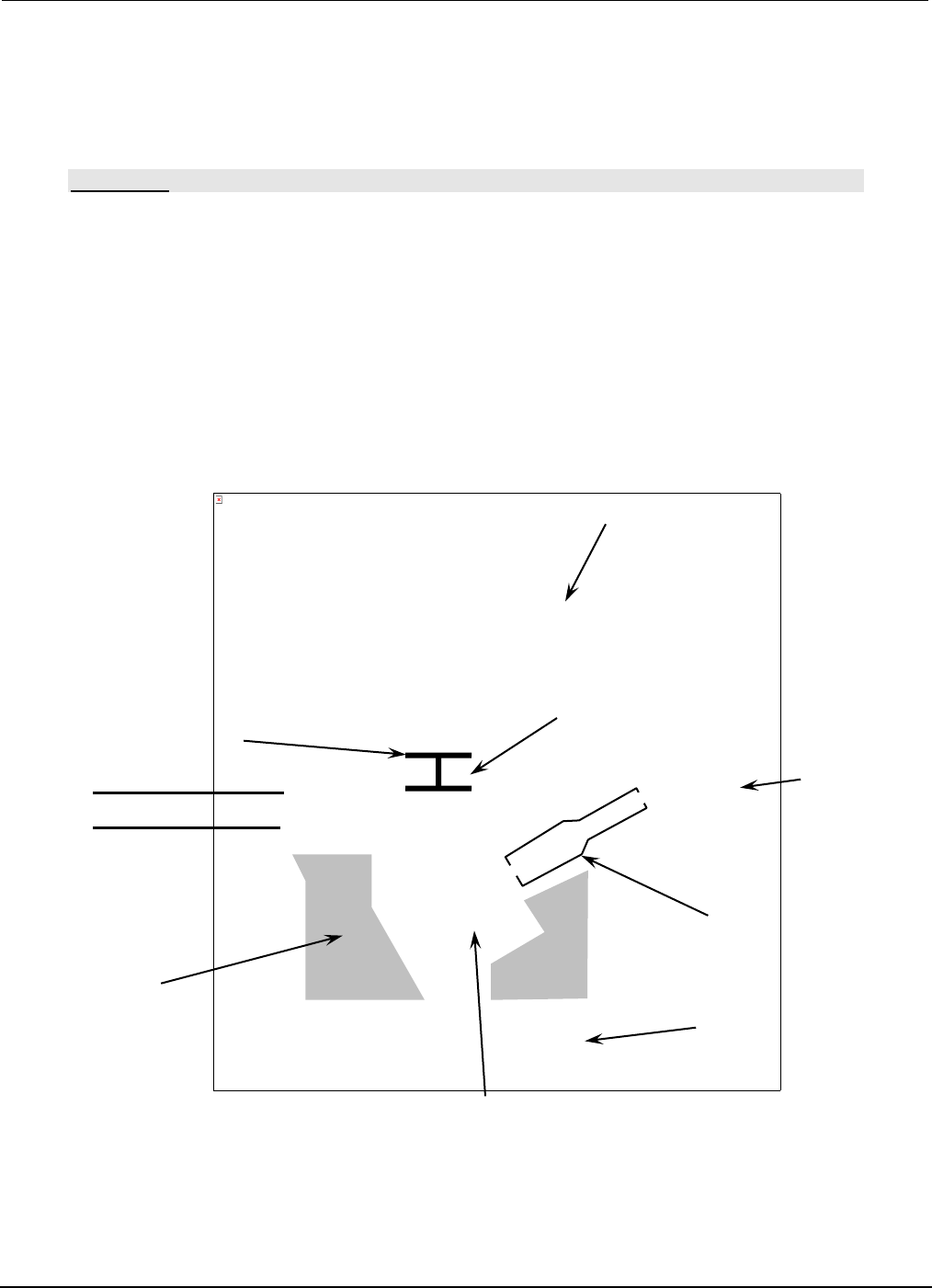
A
(B)
Solder Pot
Pump
Solder
1/2”
Solder
Level
Pump Housing
Pump Sleeve
Impeller
The picture can't be displayed.
4 Processes & Applications
4.1 Adding Solder
CAUTION:
USE INSULATED GLOVES WHEN WORKING AROUND HEATED AREA. BE CERTAIN THE MODE
SWITCH IS IN THE OFF POSITION (NEUTRAL POSITION.)
• Remove Pot Cover (A).
• Insert Baffle Assembly (B) into Pump.
• Power up system by depressing main power and reset switch on the PCBRM module.
• When the pot reaches 500°F (260°C), place solder bars into pot until solder level is reached.
• Using gloves provided, place pot cover back on pot once solder has melted.
• Power up preheater panels (for PCBRM Systems only).