PCBRM_User_Manual_R9.pdf - 第35页
PCBRM15 & PCBRM System 5.2 User’s Manual Chapter 3: Set Up & Installation Part No. 4005.00.906 3-9 Z-Axis Lock 3.5 PCBRM System 5.2 – Z Axis Stop, Set Up, Function • The z-axis lock presets a repeatable stop in t…
PCBRM15 & PCBRM System 5.2 User’s Manual Chapter 3: Set Up & Installation
Part No. 4005.00.906 3-8
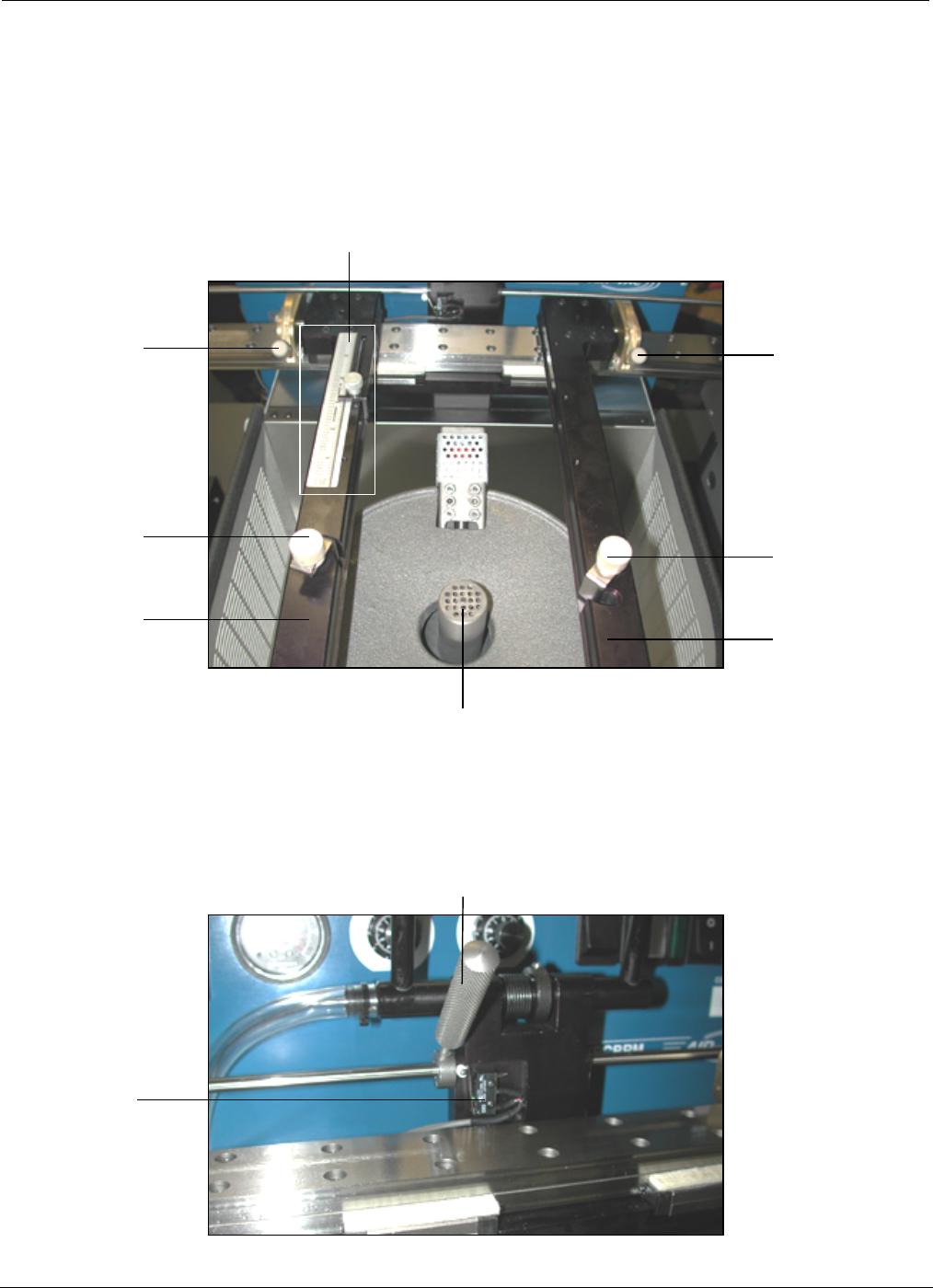
Compliant Arm Lock
Temperature
Monitor
Activation
Switch
Solder Baffle
Compliant
Arm Lock
Knobs
Y-Axis Stop and Scale
Compliant
Arm Lock
Knobs
Board
Lock Knobs
Carrier
Arms
Board
Lock Knobs
Carrier
Arms
3.4 PCBRM System 5.2 – X Axis Stops, Set Up, Function
• Locate PCB in carrier arms and lock arms in place using compliant arm lock knobs.
• Locate PCB in the y-axis and set stop.
• Lock PCB in arms using board lock knobs.
• Set x-axis stop (preheater) once PCB has been located in the preheater.
PCBRM15 & PCBRM System 5.2 User’s Manual Chapter 3: Set Up & Installation
Part No. 4005.00.906 3-9
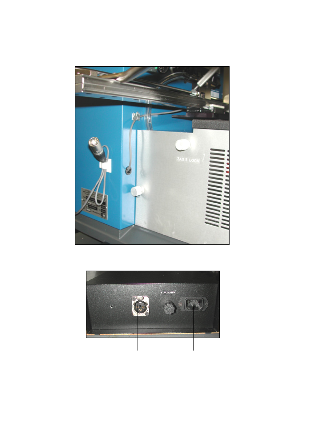
Z-Axis Lock
3.5 PCBRM System 5.2 – Z Axis Stop, Set Up, Function
• The z-axis lock presets a repeatable stop in the Z-Axis for board solder location.
Power
Receptical
Microswitch
Interface
Receptical
PCBRM15 & PCBRM System 5.2 User’s Manual Chapter 3: Set Up & Installation
Part No. 4005.00.906 3-10
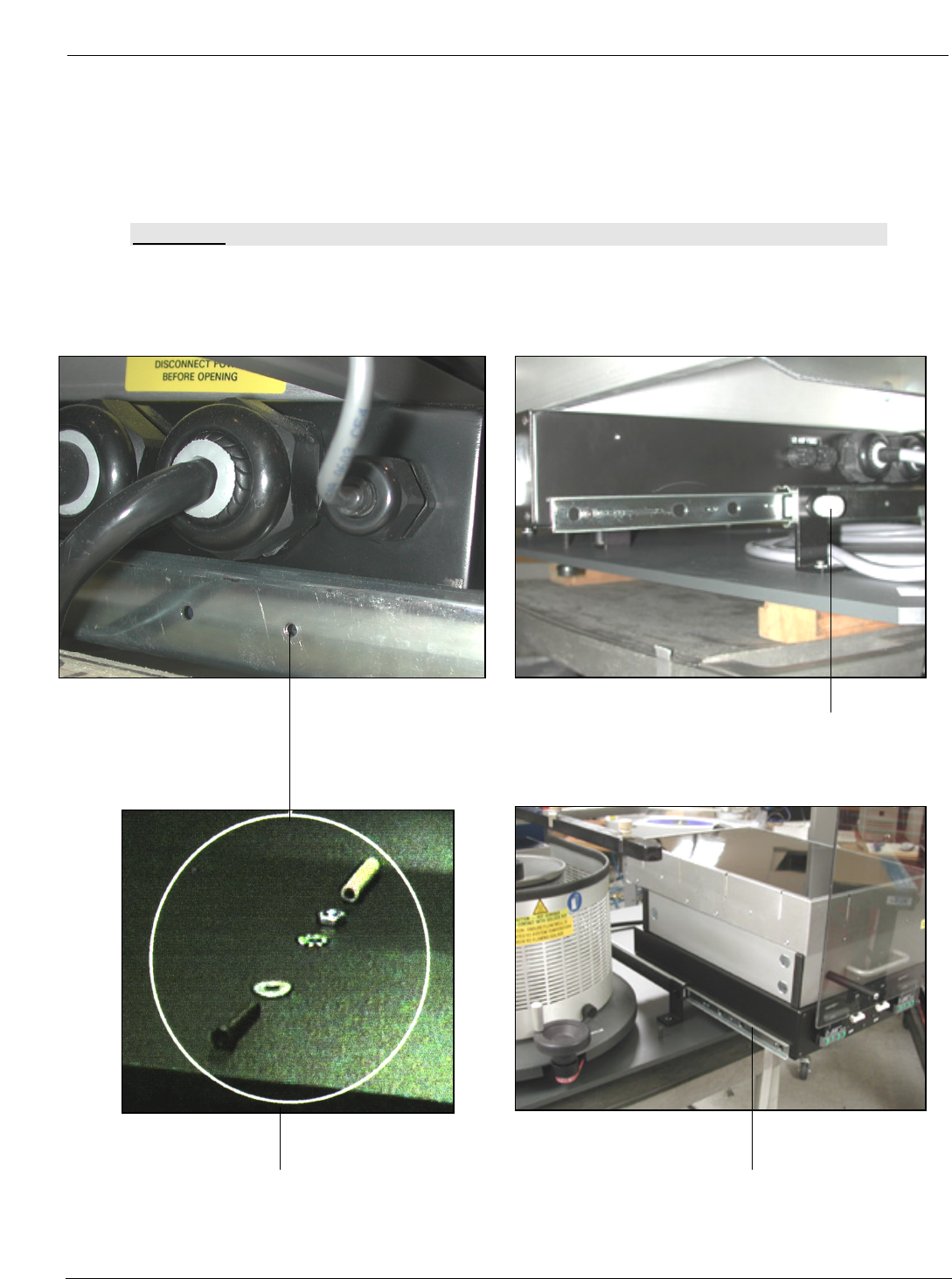
Y-Axis Preheater Lock Knob
Preheater Slides
Safety Stop
3.6 PCBRM System 5.2 - Preheater Safety Stop
• Safety Stop is removed for shipping. Install once machine is set up. Slide preheater forward and
install screw and washer into hole. Secure with lock washer and nut. Place protective tube over
the end of exposed screw.
CAUTION:
FAILURE TO INSTALL THIS STOP COULD RESULT IN DAMAGE TO SYSTEM.