PCBRM_User_Manual_R9.pdf - 第52页
PCBRM15 & PCBRM System 5. 2 User’s Manual Chapter 4: Process es & Appl icati ons Part No. 4005.00.906 4- 10 4.8 Temperature Controller (Watlow) Programmable Set Points. The Pr ogrammable Digital Readout Tempera t…

PCBRM15 & PCBRM System 5.2 User’s Manual
Chapter 4: Processes & Applications
Part No. 4005.00.906 4-9
4.5 PCB Hole Cleaning Procedure
The hole cleaning operation starts immediately at the end of the component removal procedure. Referring
back to the component removal cycle, there will be an audible signal that indicates solder has stopped
flowing against the PCB. At this point, lower the air cleaning hood. It is important that sufficient downward
pressure be applied to insure a good seal between the hood and board surface. However, excessive
pressure can force the board to contact the flow well stand offs.
Low pressure air comes on automatically 1½ seconds after the solder stops flowing, forcing the molten
solder to drop from the holes into the empty flow well. The 1½ seconds delay prevents pressurized air
from coming in contact with the flowing solder.
The bottom of the PCB may have bridging or icicling caused by the moving air. The next operation of
resoldering of the replacement component will eliminate these conditions.
4.6 Soldering Replacement Component
After the holes have been cleaned, flux the leads of the replacement component, insert into PCB, and
start the cycle to solder the component. Where leads are “free”, exert a slight downward force on the
component to prevent “floating” of the component when the solder wave contacts the leads.
4.7 Specific Production Soldering Applications
In addition to component removal and replacement, the PCBRM15 is commonly used for Selective
Soldering in the production process.
Small Sub-Assemblies
The PCBRM12 has many advantages compared to hand soldering sub-assemblies. The average solder
cycle is 5-10 seconds regardless of the number of component leads. The heat exposure on the PCB is
less, since the average solder temperature is 500°F, compared to soldering irons that are higher.
Operator skill is minimal, since the solder cycle is controlled and the entire area is soldered at once.
Seating Soldered Components
In production wave soldering, a common problem is the “floating” of components that do not have clinched
leads resulting in components that are not properly seated. These components can be positioned over
the flow well and as the solder is flowing and all joints are molten, downward force may be used to
properly seat the component.
Selective Soldering
For a variety of reasons, many components cannot be on the board during the production wave or drag
soldering and cleaning operation. These components have to be soldered on the board individually in a
secondary operation. Rather than hand soldering these components, they can be positioned over the
flow well and wave soldered without reflowing components already on the board. Very common selective
soldering applications are for edge connectors that cannot be on the board due to pallet restrictions and
components like switches and relays that cannot go through the cleaning process.
PCBRM15 & PCBRM System 5.2 User’s Manual
Chapter 4: Processes & Applications
Part No. 4005.00.906 4-10
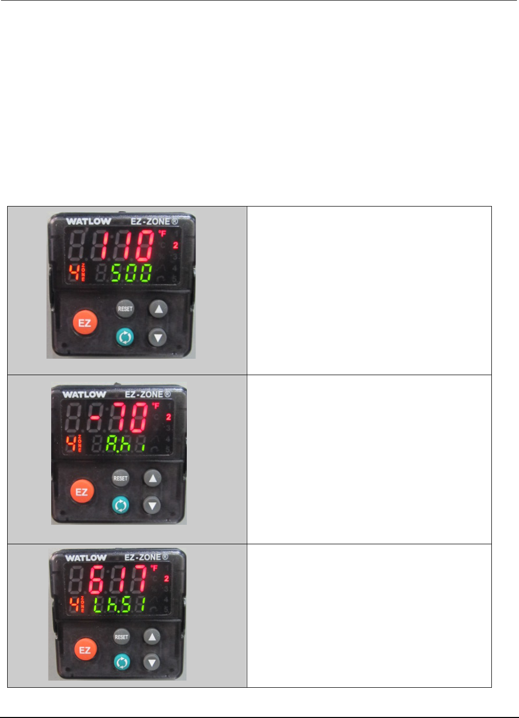
4.8 Temperature Controller (Watlow)
Programmable Set Points. The Programmable Digital Readout Temperature Controller has two set
points that are programmable. “Set point one (SP1)” is the process temperature; “set point two (SP2)” is
the standby/interlock temperature.
Process Temperature (SP1). The process temperature determines the temperature of the flowing solder
during the rework and soldering cycles. The controller is connected to a thermocouple located at the
bottom of the solder pot. The actual temperature contacting the bottom of the printed circuit board is
approximately 10°F less than the process temperature, which is factory set at 500°F.
Standby/Interlock Temperature (SP2). The standby/interlock temperatures are the same
temperature. The standby temperature minimizes oxidation by automatically reducing the temperature
when the module is not being used. The purpose of the interlock temperature is to prevent the pump
motor from operating until the solder reaches a molten condition. SP2 is factory set at 70°F less than the
process temperature (500°F - 70°F = 430°F).
1. Actual Temperature (110)
2. Process Temperature (500)
3. Standby/Interlock Temperature
(-70)
4. Overtemp Temperature (617)
PCBRM15 & PCBRM System 5.2 User’s Manual
Chapter 4: Processes & Applications
Part No. 4005.00.906 4-11
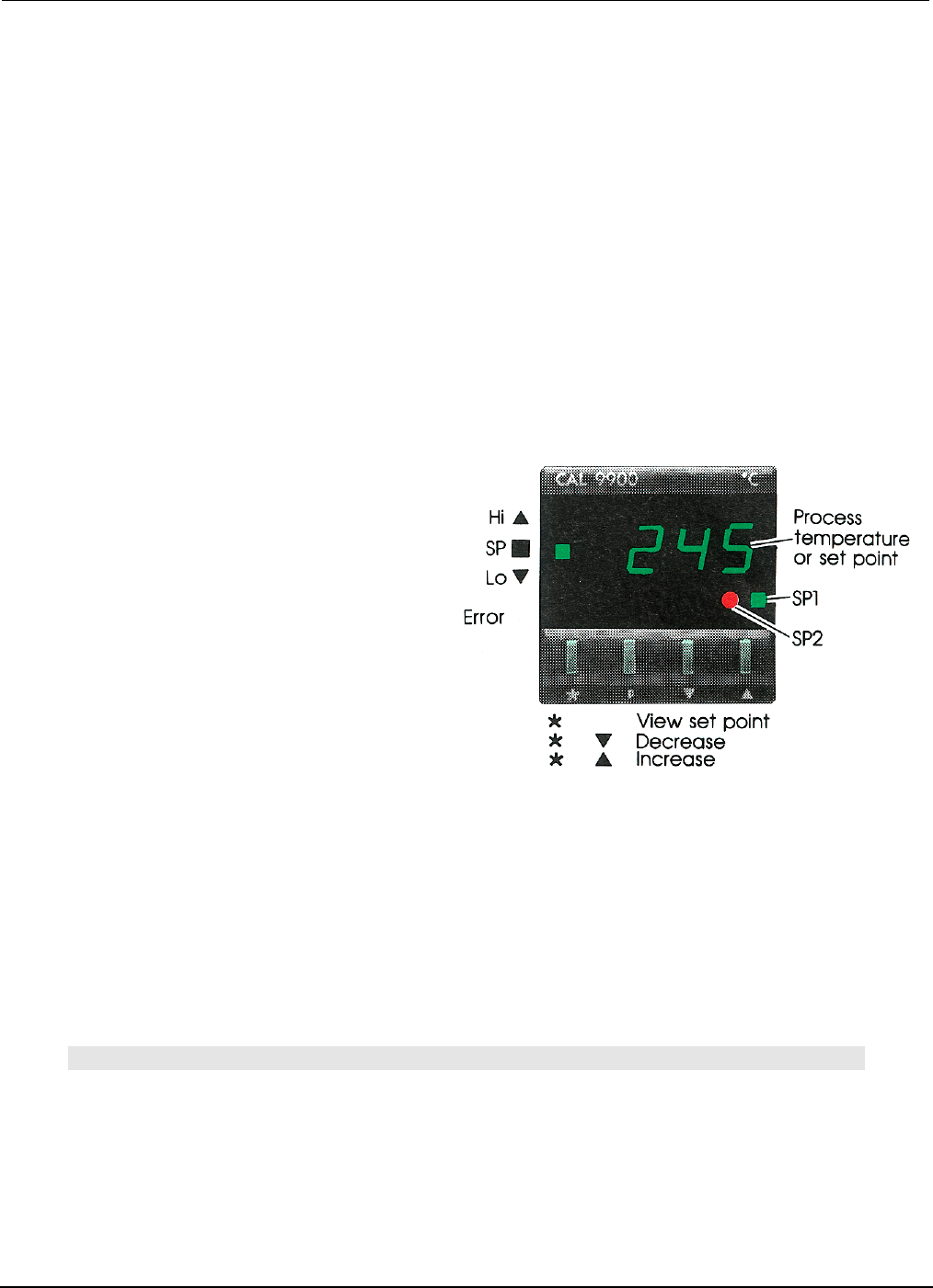
4.9 Temperature Controller (CAL 9900)
Programmable Set Points. The Programmable Digital Readout Temperature Controller has two set
points that are programmable. Set point one (SP1) is the process temperature; set point two (SP2) is the
standby/interlock temperature. The temperature selector switch determines which set point is activated.
Process Temperature (SP1). The process temperature determines the temperature of the flowing solder
during the rework and soldering cycles. The controller is connected to a thermocouple located at the
bottom of the solder pot. The actual temperature contacting the bottom of the printed circuit board is
approximately 10°F less than the process temperature, which is factory set at 500°F.
Standby/Interlock Temperature (SP2). The standby/interlock temperatures are the same
temperature. The standby temperature minimizes oxidation by automatically reducing the temperature
when the module is not being used. The purpose of the interlock temperature is to prevent the pump
motor from operating until the solder reaches a molten condition. SP2 is factory set at 70°F less than the
process temperature (500°F - 70°F = 430°F).
To Change SP1 or SP2 –
Follow These Procedures
• SP1 Temperature:
1. With the power and reset switches on,
press the *key and the SP1 setting will flash.
2. By holding the *key down and pressing the
▼ and ▲ keys, the SP1 setting may be changed.
3. When the keys are released, the display automatically returns to actual solder temperature.
• SP2 Temperature
1. With the power and reset switched on, depress the “P” key with a pointed object. The digital
display will show numbers with a decimal point and the number to the right of the decimal point
will flash.
2. Use the ▼ and ▲ keys to bring the flashing number to 2 at the right side of the decimal point.
3. Press the *key to change the left side of the decimal. Press the ▼ and ▲ keys to set the
differential temperature (range available is 0 - 99°F).
4. Press “P” to lock in memory. Display will automatically return to actual solder temperature.
Note:
SP1 AND SP2 LIGHTS WILL REMAIN LIT UNTIL EACH TEMPERATURE IS REACHED. THE ▲ LIGHT
INDICATES A TEMPERATURE HIGHER THAN PROCESS TEMPERATURE. THE ▼ INDICATES A
TEMPERATURE LOWER THAN THE PROCESS TEMPERATURE.