PCBRM_User_Manual_R9.pdf - 第73页
Pcbrm15 & PCBRM System 5.2 User’s Manual Chapter 5: Maintenance/Parts Part No. 4005.00.906 5- 5 5.3 Pump Disassembly & Cleaning CAUTION S OLDER W ILL B E H OT 7. Remove Pump Baffle (P) using needle nose pliers wh…

Pcbrm15 & PCBRM System 5.2 User’s Manual Chapter 5: Maintenance/Parts
Part No. 4005.00.906 5-4
5.1 Solder Removal
• Use Solder Bailer to transfer solder to a container with a capacity of 150 cubic inches or more.
Most of the solder can be removed with the bailer. Weight of solder is 35 lbs.
CAUTION!!
SOLDER IS HOT. USE EXTREME CAUTION.
5.2 Pump Cleaning
Pump bracket, housing, impeller and shaft are all rugged, stainless steel. The pump bearings are
lubricated with high temperature grease. Heat is not the main reason for their failure – rather it is dirt
(dross, flux).
Note:
WHEN REMOVING PUMP FOR CLEANING, SOLDER MUST BE REMOVED FROM POT.
To Clean Pump
1. Hold pump in a vise for disassembly.
2. Do not remove leveling screws.
3. Clean all parts (except pump bearings) thoroughly:
• Use mineral spirits to remove dirt.
• Use a wire brush for easy to get at areas.
• Use a scraping tool for hard to reach areas.
4. Inspect parts before reassembling (especially pump bearings). Check bearings for free, smooth
action – no binding or rough action, if so, replace.
Assembly (see Disassembly Procedure)
5. Be certain when assembling the pump housing to pump bracket that the alignment guides are
lined up exactly. This will insure that the pump is level when installed back onto the machine. If
they are not lined up or if the leveling screws were removed, the result will be an un-level solder
wave and very poor soldering or desoldering processes.
6. Spin pump shaft to be certain that the pump is assembled correctly before placing back on
machine.
Note:
O NCE PUMP IS INSTALLED ONTO THE MACHINE, CHECK THE LEVEL OF THE PUMP. IF
ADJUSTMENT IS NEEDED, REFER TO PUMP LEVELING PROCEDURE.

Pcbrm15 & PCBRM System 5.2 User’s Manual Chapter 5: Maintenance/Parts
Part No. 4005.00.906 5-5
5.3 Pump Disassembly & Cleaning
CAUTION
SOLDER WILL BE HOT
7. Remove Pump Baffle (P) using needle nose pliers while pump is in the pot with solder.
8. Remove solder from pot using ladle supplied with unit.
Note
ALLOW MACHINE TO COOL BEFORE REMOVING PUMP FROM POT.
9. Remove two screws holding pulley guard to pump.
10. Remove two screws holding pump to pot.
11. Remove two screws holding pump housing (B) to pump bracket (A) and remove housing (B).
Note
DO NOT LOOSEN OR REMOVE THE FOUR LEVELING NUTS (L) AND SET SCREWS (M) OR THE
PUMP WILL NEED TO BE RE-LEVELED UPON INSTALLATION.
12. Loosen the two set screws on the pump pulley (G).
13. Remove the two bearing retaining screws (H) and washer (I).
14. Slide the pump shaft (D) with impeller (C) out of the pump bracket (A). Pump sleeve (N) will
drop away at this point.
15. Remove pump bearings (E), spacer (F) and pulley (G) from pump bracket (A).
Note
INSPECT BEARINGS FOR SMOOTH MOVEMENT. REPLACE IF NECESSARY.
16. Remove pump shaft (D) from impeller (C) and discard.
17. Remove pump sleeve insert (R) and discard.
18. Clean all parts of solder and dirt using a wire brush or a tool to scrape solder from pieces.
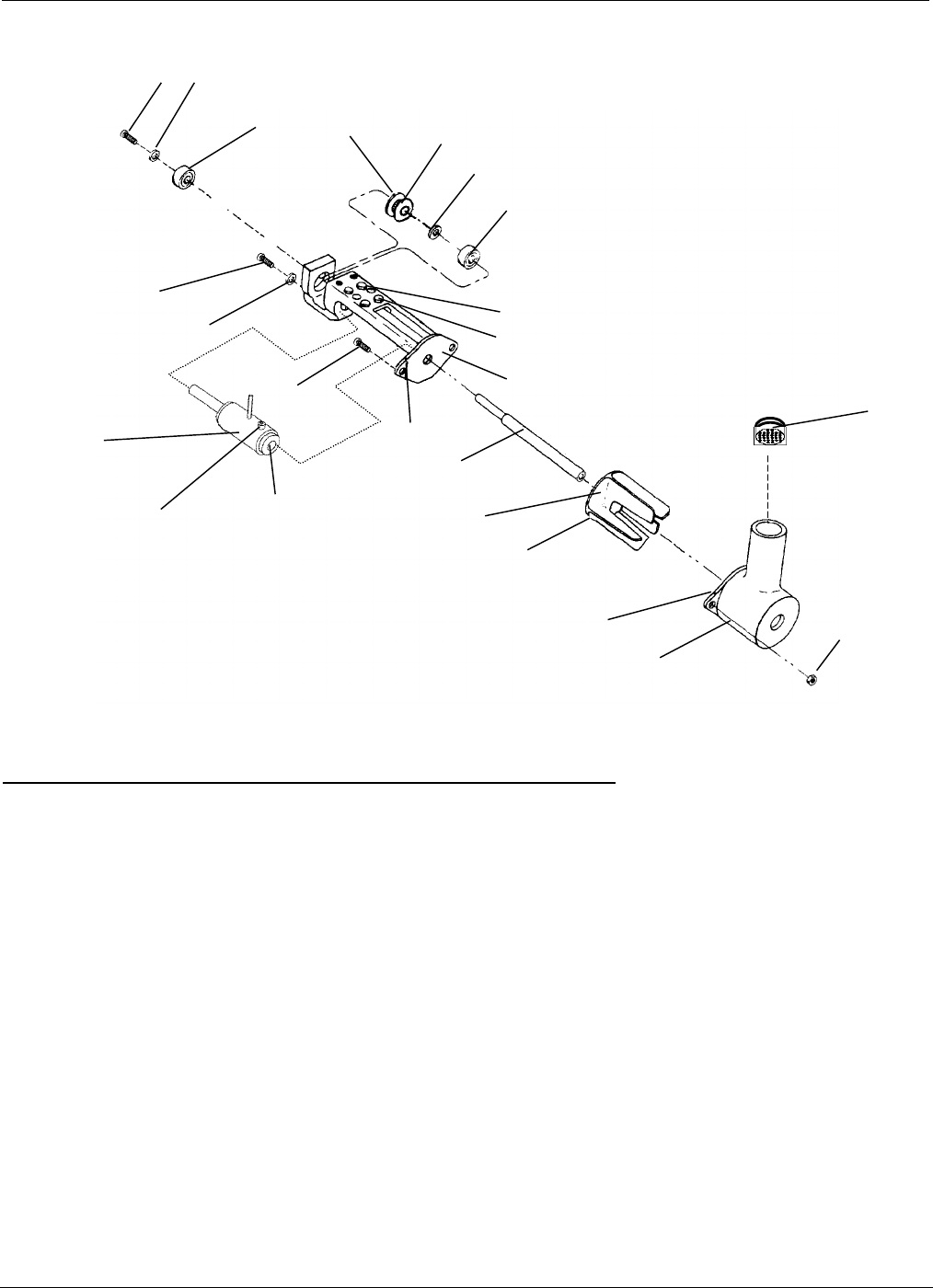
19. Re-assemble pump as shown in drawing as follows:
• Insert lower bearing into pump bracket.
• Turn bracket upside down and insert pulley (hub side) into upper bearing hole.
• Place spacer on top of pulley.
• Insert shaft into bracket, through pump sleeve, bearing spacer and pulley.
• Turn bracket over and insert upper bearing.
• Install bearing retaining screws (H) and (I).
• Tighten pulley set screws.
• Install impeller onto shaft – before tightening the set screw be certain the play from the
shaft and bearings will not cause impeller to hit pump bracket face. Allow for this
clearance before tightening set screw.
• Spin shaft with fingers and check for any interference. Correct as required.
• Install pump housing (B) to bracket (A). Be certain the index marks are aligned exactly
before tightening. If they are not, the pump will not be level.
• Spin shaft with fingers and check for any interference between impeller and housing.
20. Pump is now ready for installation back into pot. Use anti-seize on the mounting screws when
installing. Alternate tightening screws until snug. DO NOT OVERTIGHTEN. Over-tightening
could cause pump to become un-level.
21. Check level of pump to carrier arms. Re-level if required.
Pcbrm15 & PCBRM System 5.2 User’s Manual Chapter 5: Maintenance/Parts
Part No. 4005.00.906 5-6
Item Description Qty. Part# (PCBRM15)
- Pump Assembly-PCBRM15 1 2004.01.044
A Pump Bracket 1 2004.01.102 (gray iron)
B Pump Housing 1 2004.01.101 (gray iron)
C Pump Impeller 1 2004.01.100 (gray iron)
D Shaft 1 2004.01.103 (titanium)
E Bearing 2 9001.09.020
F Spacer 1 12464
G Pulley 1 12453
H Screw, 6-32 x 1/4 Button Hd 2 60A
I Washer, #6 SAE 2 9A
J Screw, 10-32 x 5/8 2 9000.00.000 (titanium)
K Nut, 10-32 2 9000.06.002 (titanium)
L Nut, 6-32 x 4 8B
M Set Screw, 6-32 x 5/16 4 11A
N Pump Sleeve Assembly 1 2004.01.041 (titanium)
O Set Screw, 10-32 x 3/8 1 9000.10.249 (titanium)
P Baffle Assembly 1 2004.01.043 (titanium)
Q Pump Mounting screws (10-32 x _) 2 23A
R Pump Insert 1 12418
H
I
E
G
F
E
M
L
A
H
I
J
N
Index Mark
D
C
B
K
upper
HUB
This side
Index Mark
O
P
.
NOTE 1:
When cleaning of pump is required, the pump shaft (D) and the
pump sleeve insert (R) need to be replaced.
R
See note 1
See note 1
9000.02.000