00195166-0402_SM_D4_EN.pdf - 第104页
Service Work Component Handling Cutter 104 Serv ice Manual SIPLACE D4 Installing the articulated joint and sh ort-stroke cylinder X Apply a small amount of Loctite no. 243 to th e thread of the new joint. X If the enamel…
Service Work
Cutter Component Handling
Service Manual SIPLACE D4
103
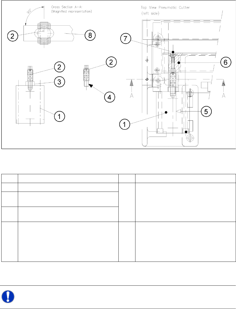
4-36: Removing Articulated Joint, Installing It on New Master Cylinder and Bonding It in Place
Legend
X Dismantle the articulated joint (2) from the cylinder (1) by turning the open-end wrenches
(SW 11, 14) on the surfaces marked (3) .
1 Short-stroke cylinder (1 or 2) 6 Slide surface of the movable blade
2 Articulated joint (complete) 7 Screw fastening the articulated joint to the
movable blade:
One M4 x 24 DIN 912 socket hex head cap
screw each, strength 12.9, secured with Loctite
no. 243
3 Wrench surface for disassembling the
articulated joint
4 Secure articulated joint thread with Loctite no.
243
5 Open-end wrench surface of articulated joint 8 Movable blade with slot to prevent the
articulated joint from turning if the articulated
joint is damaged, use a (complete) new one
(article no.: see ) or clean the residues of Loctite
from the thread of the existing articulated joint
pin.
NOTE:
The threaded pin is secured with Loctite no. You will need somewhat more strength than usual
to loosen it.

Service Work
Component Handling Cutter
104 Service Manual SIPLACE D4
Installing the articulated joint and short-stroke cylinder
X Apply a small amount of Loctite no. 243 to the thread of the new joint.
X If the enamel on the one-way restrictor is damaged use a new "short-stroke cylinder".
WARNING: There is a high risk of injury from the blades and the tape deflector!
CAUTION:
Tighten the screws to the correct torque.
DANGER:
One-way restrictors may not be set at the machine. This is only permitted at the factory.
For this reason the replacement short-stroke cylinder must always be installed, together with the
new, already adjusted restrictors attached to it.
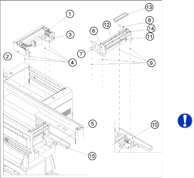
4-37: Removing Articulated Joint, Installing It on New Master Cylinder and
Bonding It in Place
X Screw the articulated joint into the short-stroke
cylinder.
X Turn the articulated joint into the installation
position.
Once the cylinder is installed, the slot in the
moveable blade prevents the articulated joint
from turning.
X Copy the exact mounting position of the
proximity switch to the short-stroke cylinder
(feeler gauge, fine-tip marker).
X Install the prepared cylinder - complete with
one-way restrictors - on the cutter, in the
correct rotational position for the articulated
joint.
X Fasten the cylinder in this position, with the 2
M5x65 screws (2) provided.
X Install the proximity switch (Item No. see
section 5.2) precisely in the position you
marked on the short-stroke cylinder with the
permanent marker (4, 5).
X Connect the compressed air hoses to the one-
way restrictor on the cylinder, in the correct
allocation (see markings).
One-way restrictor (for running cylinder out)
(6)
One-way restrictor (for running cylinder in) (7)
Allocation of the compressed air connections,
pneumatic hoses (8)
Service Work
Cutter Component Handling
Service Manual SIPLACE D4
105
See also:
J
Tightening Torques for Cutter Screws [
J
87]
J
6.4.3 Check the gap between the empty-tape baffle, inside and the leading edge of the tape deflector.
[
J
241]
J
4.3.2.14 Final Steps [
J
114]
X Perform the following steps as described in
section (4.3.2.7 Replacing the Stationary Bla-
de and Movable Blade incl. Spacers
J
95 ) :
Fasten the moveable blade to the articulated
joint.
X Fit the empty-tape duct (6) on the machine
base (2 screws each on the left and right (9)).
X Check the gap between the empty-tape baffle,
inside and the leading edge of the tape
deflector.
X Check the switching points of the proximity
switches. (See section (4.3.2.11 Exchanging
the Inductive Proximity Switch
J
110 ) .)
NOTE:
If the tapes are not cut correctly, even
though the switching points are set
properly and the short-stroke cylinder
has been exchanged, complete with
the one-way restrictor, the cause of the
problem may be:
X Incorrect compressed air value/
leaky pneumatic connection
X Y socket union
X Blade in poor condition
X Faulty solenoid valve or
X Interruption of solenoid valve
activation
X Perform the appropriate “Final Steps”.