00195166-0402_SM_D4_EN.pdf - 第56页
Service Work Electrical System Measuring the Power Supply U nit 56 Serv ice Manual SIPLACE D4 4.1.2.3 Measuring volt ages at transformer T1 Primary side of transformer T1 The transf ormer can be connect ed to the follo w…
Service Work
Measuring the Power Supply Unit Electrical System
Service Manual SIPLACE D4
55
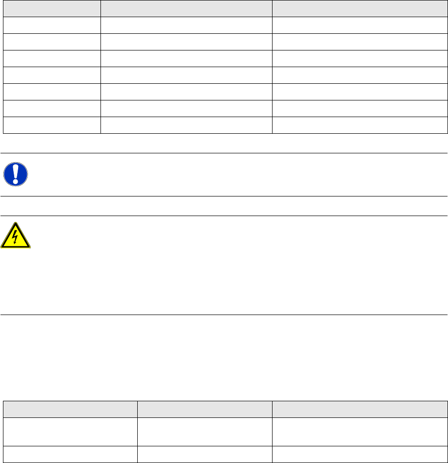
Measuring voltages at main power filter Z1 and electrolytic capacitor C1
The diagram above shows the position of the power supply filter and the electrolytic capacitor C1.
4 main power filters for 36 A 3-phase systems
10 electrolytic capacitors 33000 µF / 63 V
Rectifiers Input Output
V1 3 x 140 VAC 200 VDC
V2 150 VDC 150 VDC
V3 3 x 32.5 VAC 40 VDC
V4 3 x 32.5 VAC 40 VDC
V5 3 x 8.14 VAC 8 VDC
V6 3 x 40.7 VAC 48 VDC
V7 3 x 24.4 VAC 24 VDC
NOTE:
X Remember to replace the perspex safety panels over rectifiers V1 and V7 when the
measurements are complete.
DANGER: RISK OF DEATH BY ELECTRIC SHOCK
X Switch the placement system off at the main switch.
X Disconnect the placement system from the power supply.
X Wait approximately 1 minute until the residual voltages have dropped to a safe level
(electrolytic capacitor C1).
X Attach the perspex safety panel and fix in place with the M5 fillister head screws.
CAUTION Do not overtighten the fillister head screws. The perspex panel might break.
Assembly Terminal Voltages
Main power filter Z1 L1, L2, L3 3 x 204 V~ / 3 x 230 V~ / 3 x 380 V~ /
3 x 400 V~ / 3 x 415 V~
Electrolytic capacitor C1 + / - 52 VDC
Service Work
Electrical System Measuring the Power Supply Unit
56 Service Manual SIPLACE D4
4.1.2.3 Measuring voltages at transformer T1
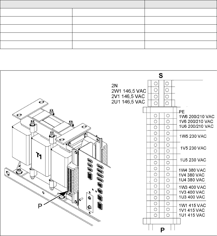
Primary side of transformer T1
The transformer can be connected to the following main power supplies:
3 x 230 VAC for the "on-board electrical system" is drawn at terminals 1U5, 1V5 and 1W5. This is used
to supply the PC and the monitor.
4-4: Primary terminals of transformer T1
Voltage Terminals
3 x 200-210 V~ (U.S.A) ± 5 %, 50/60 Hz 1U6, 1V6, 1W6
3 x 230 VAC ± 5 %, 50/60 Hz 1U5, 1V5, 1W5
3 x 380 VAC ± 5 %, 50/60 Hz 1U4, 1V4, 1W4
3 x 400 VAC (Europe) ± 5 %, 50/60 Hz 1U3, 1V3, 1W3
3 x 415 VAC ± 5 %, 50/60 Hz 1U1, 1V1, 1W1
Service Work
Measuring the Power Supply Unit Electrical System
Service Manual SIPLACE D4
57
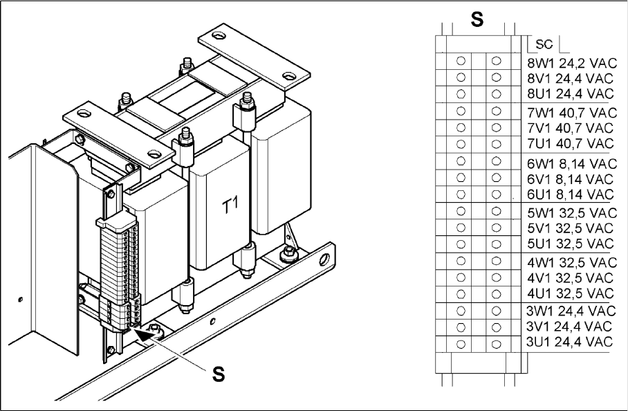
Secondary side of transformer T1
4-5: Secondary terminals of transformer T1
Transformer T1 supplies the following voltages on the secondary side:
3 x 24.4 VAC
3 x 40.7 VAC
3 x 8.14 VAC
3 x 32.5 VAC
3 x 32.5 VAC
3 x 24.4 VAC