00195166-0402_SM_D4_EN.pdf - 第230页
Settings C&P12 Determining the Zero Point Correction for the Star Axis of the C&P H ead 230 Serv ice Manual SIPLACE D4 6.3.9 Determining the Zero Point Correctio n for the S tar Axis of the C&P Head 6-17: Flo…
Settings
Setting the Light Barrier Down C&P12
Service Manual SIPLACE D4
229
X Check whether the 5/100 mm feeler gauge passes easily (without resistance) between the Z axis
end stopper and the tension jack (see diagram above).
X If this is not the case, you will need to adjust the Z axis end stopper setting!
X Loosen the Z axis end stopper screw.
X Clamp a 15/100 mm feeler gauge between the Z end stopper and the clamp. Gently press the Z axis
end stopper downwards with the screwdriver and screw tight.
X It should now be more difficult to extract the 15/100 mm feeler gauge.
X Check again whether the 5/100 mm feeler gauge passes easily (without resistance) between the Z
axis end position stop and the tension jack. If this is not the case, you will need to readjust the setting!
6.3.8 Setting the Light Barrier Down
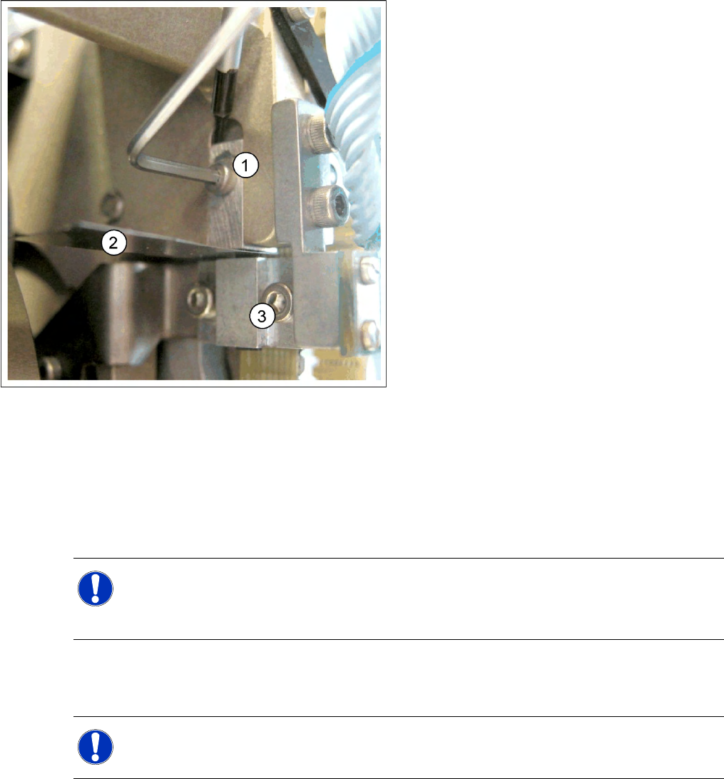
6-16: Z end stopper check and adjust
Legend
1. Z end stopper
2. Feeler gauge
3. Clamping device
NOTE:
When removing the gauge, make sure that the gauge pin is extracted first and that then the star
gauge is removed. If you do not observe this order, the gauge could catch in the segments and
damage these!
NOTE:
The light barrier is set with a test probe to a distance of 1.0 mm to the sleeve.
Settings
C&P12 Determining the Zero Point Correction for the Star Axis of the C&P Head
230 Service Manual SIPLACE D4
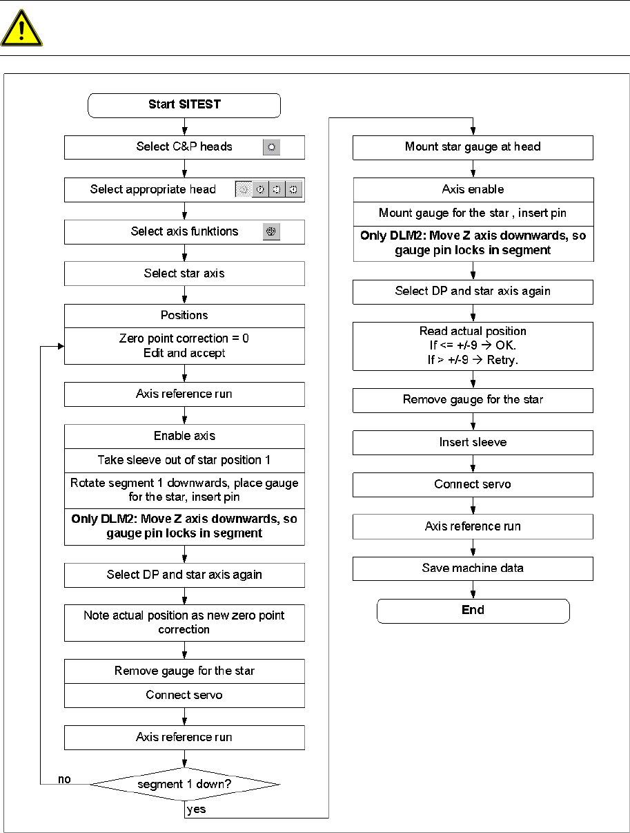
6.3.9 Determining the Zero Point Correction for the Star Axis of the C&P Head
6-17: Flow chart zero point correction
ATTENTION:
X When performing this task, follow all instructions exactly!
Settings
Setting the Mechanical Position of the Valve Positioning Drives C&P12
Service Manual SIPLACE D4
231
6.3.10 Setting the Mechanical Position of the Valve Positioning Drives
Set the motor position of the valve positioning drives "pickup/placement" and "reject" as shown in the
following diagram.
If the new valve plungers are used (s. diag. below) proceed as follows: Take out one valve plunger
and remove the sleeve (2).
Insert the plunger without bushing and carry out the following steps on this segment:
Insert the distance gauge (0.2 mm) between valve plunger and valve casing.
Rotate the valve positioning drive 90 degrees from its initial position. The eccentric of the valve
adjustment drive will just touch the inner side (1) of the valve plunger.
Fix the motor of the valve drive in this position.
Remember to replace the tube on the valve plunger.
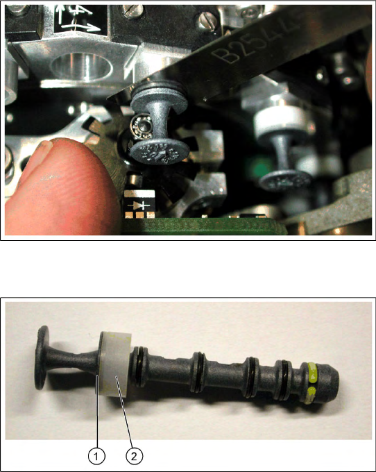
6-18: Setting the mechanical position of the valve drive
Set the motor position of the valve positioning
drives "pickup/placement" and "reject" as shown in
the diagram.
6-19: New valve plunger [00351498-03]
X If the new valve plungers are used (s. diag. on
left) proceed as follows:
Take out one valve plunger and remove the
sleeve (2).
Insert the plunger without bushing and carry
out the following steps on this segment:
X Insert the distance gauge (0.2 mm) between
valve plunger and valve casing.
X Rotate the valve positioning drive 90 degrees
from its initial position. The eccentric of the
valve adjustment drive will just touch the inner
side (1) of the valve plunger.
X Fix the motor of the valve drive in this position.
X Remember to replace the tube on the valve
plunger.