00195166-0402_SM_D4_EN.pdf - 第253页
Settings Function "Constant Transport Time in Placement Area" Conveyor Service Manual SIPLACE D4 253 6.5.7 Function "Const ant T rans port T ime in Placement Area" 6-37: Diagrams of PCB braking The au…
Settings
Conveyor Setting the Laser Light Barrier for the Stopper Position
252 Service Manual SIPLACE D4
Procedure
X Set the maximum conveyor width.
X Choose General functions --> Cycle mode --> Safety mode switch on.
X Activate the relevant laser diode using the input/output functions in SITEST.
X Check the path of the laser beam by covering the front edge of a board with a white label and moving
it into the placement area.
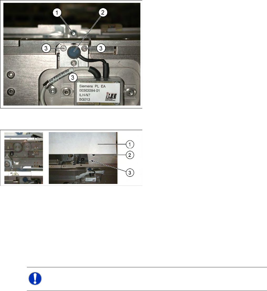
X With the help of the three setting screws, adjust the laser beam to the center of the receiver.
X Check the PCB reference corner and reteach, if necessary.
6-35: Laser light barrier
Legend
1. Laser receiver
2. Laser diode
3. Setting screws (3x)
6-36: Focussing the laser beam
Legend
1. Paper
2. Visible laser beam
3. Board parallel to laser beam
NOTE:
When you move the paper, the beam must follow along the edge of the PCB as accurately as
possible, with minimal deflection to the left and right.
Settings
Function "Constant Transport Time in Placement Area" Conveyor
Service Manual SIPLACE D4
253
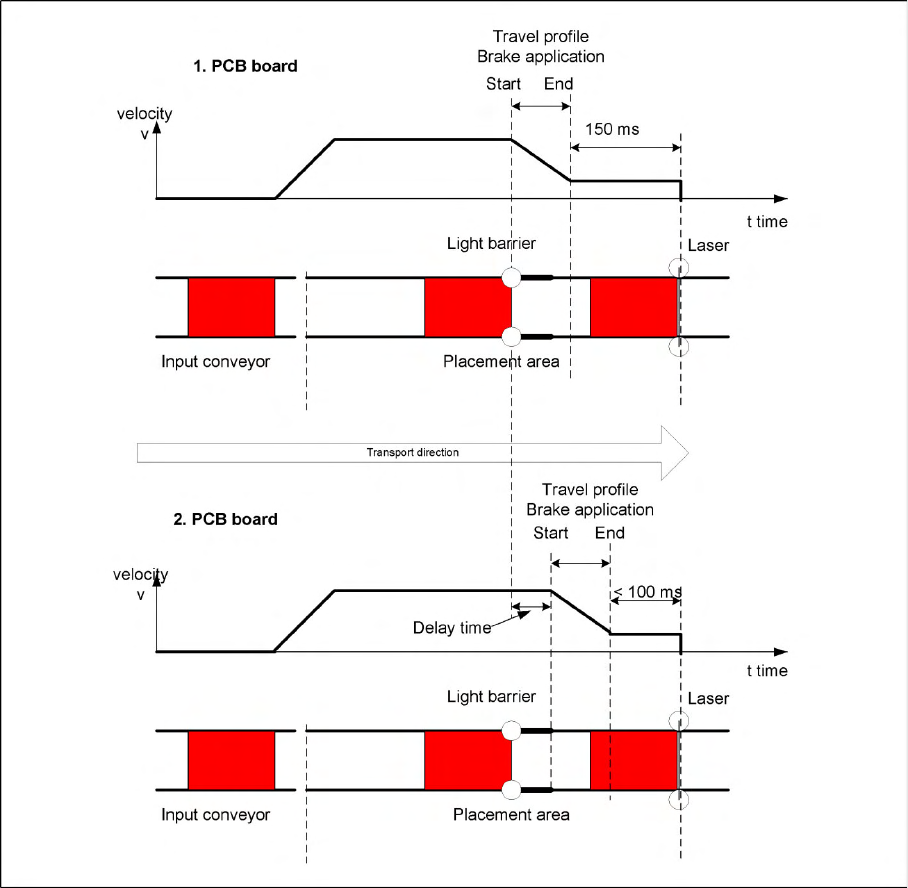
6.5.7 Function "Constant Transport Time in Placement Area"
6-37: Diagrams of PCB braking
The automatic teaching at the beginning of the travel profile guarantees that the stopper is always
reached in the same time, irrespective of the board weight. The transport time remains the same.
Function:
Switching on the laser light barrier
Starting the board braking procedure.
The light barrier in the placement area is used to recognize the board and then start the braking
procedure (travel profile) via the conveyor control software. The software automatically "teaches" the first
board how to move in slow approach mode. Once the travel profile for braking the PCB has begun (on
time), the PCB will be reliably stopped at the laser light barrier, after a maximum of 100ms.
Settings
Conveyor Light Barrier Functions in Input, Intermediate and Output Conveyors
254 Service Manual SIPLACE D4
6.5.8 Light Barrier Functions in Input, Intermediate and Output Conveyors
Recognizing and stopping the PCB boards.
Monitoring the boards in the input conveyor i.e.
If a board is recognized in the input conveyor, it will appear on the operating interface and the
machine will lock the conveyor interface to the previous station. When using boards with outbreaks,
the board may stop although the signal of the light barrier is disabled and the interface to the previous
station is opened again. Then the next PCB would move into the input conveyer with the PCB still
lying in the input conveyer. The board monitoring function moves the board backwards and then
transports it forwards again, until the light barrier switches.
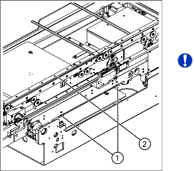
6.5.9 Setting the Clamping Actuator
Legend
1. Actuator
2. Top edge of conveyor belt
X Set the distance between the actuator and the
top edge of the conveyor belt to 94 mm.
NOTE:
The distance between the clamping
actuator (lifting table) and the top edge
of the belt must be checked at all four
contact points.