00195166-0402_SM_D4_EN.pdf - 第81页
Service W ork Changeover Table Component Handling Service Manual SIPLACE D4 81 4.3.1.4 Replacing the Communication Unit (Feed er Control Unit) [03002179-xx] See also: J 4.3.1.6 Final Steps [ J 83] 4-27: Replacing the c…
Service Work
Component Handling Changeover Table
80 Service Manual SIPLACE D4
4.3.1.3 Replacing the Fixed and/or Guide Castors
Parts
2x fixed castor [03044881-xx]
2x double guide castor [03050704-xx]
Removal/Installation
The changeover table is dismantled and prepared, as described in section (4.3.1.2 Preparations for Ser-
vice Work
J
79 ) .
X Tear down the changeover table and remove the partition plates in the tape container.
X Enlist the aid of a 2nd strong person and place the changeover table on its side (1).
X Undo the screws fastening the fixed castor and/or guide castor to be exchanged (size 6 Allen
wrench: ).
X Insert the new guide castors and/or fixed castors and fix these back into place with 4 hexagon
socket-head screws each.
X With the aid of a 2nd strong person, set the changeover table back up.
Secure the changeover table to prevent it from rolling away by itself.
X If you have no further parts to be replaced, perform the appropriate "Final Steps" (see section
(4.3.1.6 Final Steps
J
83 ) ).
See also:
J
4.3.1.1 Safety Instructions [
J
78]
WARNING:
The changeover table needs to be laid on its side to remove the fixed castor and/or guide castor.
Two people are required for this as the changeover table is very heavy.
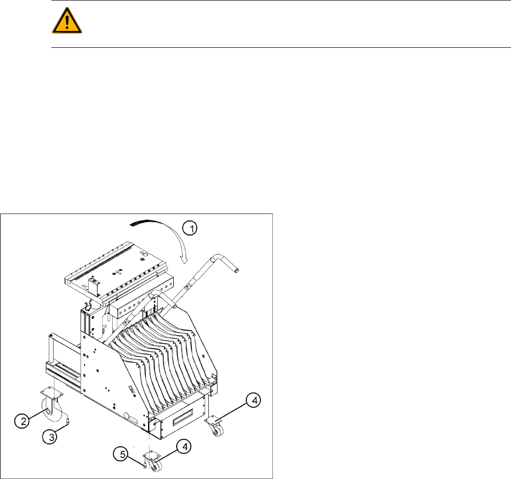
4-26: Replacing the fixed and guide castors (D4 shown as example)
Legend
1. Lay the changeover table on its side (2nd
person required) before removing the rollers.
2. Fixed castors (2 units)
3. 8 hexagon socket-head screws M8 x 16
4. Double guide castors (2 units)
5. 8 hexagon socket-head screws M8 x 16
Service Work
Changeover Table Component Handling
Service Manual SIPLACE D4
81
4.3.1.4 Replacing the Communication Unit (Feeder Control Unit) [03002179-xx]
See also:
J
4.3.1.6 Final Steps [
J
83]
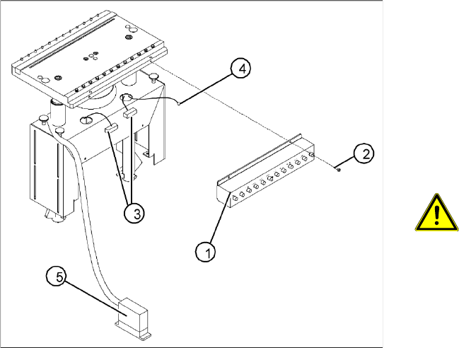
4-27: Replacing the communications unit; view of the changeover table
connection area (D4 shown as example)
Legend
1. Communication unit (Feeder Control Unit)
2. Fasteners for the communications unit: 2 M 4
x 6 hexagon socket-head screws
3. "Changeover table" connection cable
4. Ground cable with cable shoe
5. "Changeover table" connection cable -
connector
ATTENTION:
The same fastening screws can be
used to fit a splice detection unit. Bear
this in mind when loosening the
screws.
X Perform the "Preparatory Steps" (see section
(4.3.1.2 Preparations for Service Work
J
79
) ).
You do not need to dismantle the feeder
modules.
X Unplug the two press-fit connections for the
"changeover table“ cable, at the back of the
communication unit housing (3) and remove
the ground cable (4).
X Hold the communication unit and undo the
fastening screws (2).
X Remove the communication unit (1).
X Place the new communications unit on the
retaining brackets and tighten the screws to
fasten it.
X Reconnect the "changeover table" cable at the
back of the communications unit housing.
X If you have no further parts to be exchanged,
perform the appropriate "Final Steps",
including a table function check with SITEST.
Service Work
Component Handling Changeover Table
82 Service Manual SIPLACE D4
4.3.1.5 Replacing the Changeover Table Connection Cable
Power supply cable "changeover table"
X Perform the "Preparatory Steps". (See section (4.3.1.2 Preparations for Service Work
J
79 ) .)
You do not need to dismantle the feeder modules.
X Unplug plugs X13 and X15 of the communication unit cable.
X Disconnect the pneumatic hose.
X Disconnect the ground cable at the connection provided.
X The ground cable is looped through the changeover table and fastened at several connections.
To avoid weaving out the complete ground cable, disconnect the cable at the cable shoe.
X Open the cord grip and remove the entire cable.
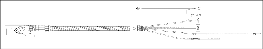
4-28: Cable for changeover table (D4 shown as example)
X Feed the new cable into the cord grip from the top to the bottom.
X Plug in the communication unit connection cable and reconnect the pneumatic system.
X Run the cable and attach cable ties.
X If you have no further parts to be exchanged, perform the appropriate "Final Steps", including a table
function check with SITEST.
See also:
J
4.3.1.6 Final Steps [
J
83]