00195166-0402_SM_D4_EN.pdf - 第95页
Service W ork Cutter Component Handling Service Manual SIPLACE D4 95 X Remove the parallel clamps from the cu tter or dismantle the cutter from the mounting plate. X Fit th e cutter back into th e machine.(See section (4…
Service Work
Component Handling Cutter
94 Service Manual SIPLACE D4
Installing the Blades
X Afterwards, rotate the stationary blade 180° on its vertical axis to the original installation position,
insert it into the cutter in this position and screw it tight. The right-hand end of the blade must now
be on the left!
X Fit the stationary blade.
X Assemble the cutter in the reverse order to disassembly.(See section (4.3.2.7 Replacing the Statio-
nary Blade and Movable Blade incl. Spacers
J
95 ) .)
WARNING: Risk of injury!
X Wear appropriately thick protective gloves!
X There is a high risk of injury from the blades and the tape deflector.
X Never reach into the cutter from below or into the empty-tape duct from above.
CAUTION:
Tighten the screws to the correct torque.
Make sure all parts are clean before installing them!
Do not use grease dissolving agents for cleaning!
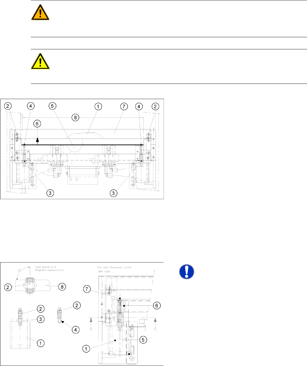
X Wear appropriately thick protective gloves!
X Make sure that the blades (1, 5) are clean. If
they are not, wipe all of their surfaces very
carefully with a clean cloth which has been
folded several times.
X Turn the movable blade 180 ° on its vertical
axis to the previously marked installation
position:
X Insert the movable blade into the cutter, in this
angle of rotation and push it in parallel, back
into the original mounting position.
X Apply Loctite no. 243 to the two M4 screws (4),
to fasten the joint in the moveable blade.
X Reinsert these screws in the left and right of
the movable blade.
X Align the articulated joint (3) so that the slanted
side of the blade engages with the slot in the
blade.
NOTE:
Make certain that the midline / open-
end wrench surface of the articulated
joint (2) is at right angles to the slide
surface of the movable blade (5, 6), so
that the articulated joint can slide
smoothly in the slot (= prevents turning)
of the movable blade (8) .
X Use the size 11 open-end wrench to hold the
appropriate articulated joint (2) and tighten the
two screws (7) .
Service Work
Cutter Component Handling
Service Manual SIPLACE D4
95
X Remove the parallel clamps from the cutter or dismantle the cutter from the mounting plate.
X Fit the cutter back into the machine.(See section (4.3.2.5 Exchanging the Pneumatic Cutter
J
87 ) .)
X Fit the empty-tape duct assembly and check the gap between the empty-tape baffle, inside and the
leading edge of the tape deflector.
X Perform the "Final Steps".
See also:
J
Tightening Torques for Cutter Screws [
J
87]
J
6.4.3 Check the gap between the empty-tape baffle, inside and the leading edge of the tape deflector.
[
J
241]
J
4.3.2.14 Final Steps [
J
114]
4.3.2.7 Replacing the Stationary Blade and Movable Blade incl. Spacers
Removing the Old Blades incl. Spacers
WARNING:
X Wear appropriately thick protective
gloves!
X There is a high risk of injury from the
blades and the tape deflector.
X Never reach into the cutter from
below or into the empty-tape duct
from above.
X Make sure that no-one can injure
themselves on the cutter, after it has
been dismantled and placed next to
the machine!
NOTE:
X The stationary blade and the
movable blade, including the
spacers, must always be exchanged
as a set, if both cutting edges are
blunt.
X The blades which are removed can
be reground at the factory (S,3/$&(
facility).
X Remove the cutter from the machine. (See
section (4.3.2.5 Exchanging the Pneumatic
Cutter
J
87 ) .)
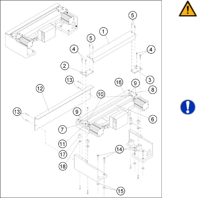
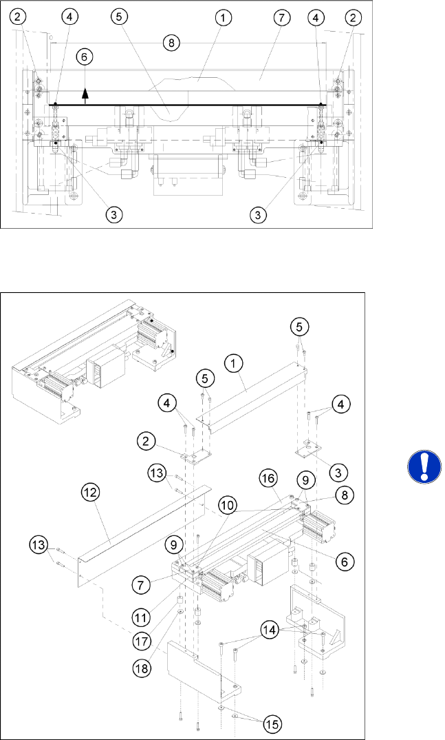
X Dismantle the deflector plate (12): 4 hexagon
socket-head screws M4 x 8 (13).
Service Work
Component Handling Cutter
96 Service Manual SIPLACE D4
X Loosen the screws fastening the stationary
blade on the left and right (2).
X Mark the mounting position of the stationary
blade (on the blade) with a water-insoluble
marker (= right end = right).
X Before any further disassembly, fasten the
dismantled cutter to the retaining bracket (LH
and RH) with 2 parallel clamps, on a flat sturdy
work bench, or screw it tight to the mounting
plate with four M6 hexagon socket head
screws
X Remove the stationary blade. (See section
(4.3.2.6 Turning the Stationary and Moveable
Blade by 180 °
J
92 ) .)
X Loosen the fixtures on the left and right tape
deflector holders above the movable blade (2
screws each on the left and right, outer edge
(7, 9). Do not loosen the two Phillips screws
(10).
X Remove the tape deflector holder (incl. cover
plate and tape deflector) and set this unit down
carefully (with the tape deflector up).
NOTE:
X Only version 03 holddowns are to be
used for version 04 cutters (= with
tape deflector).
X The spacers removed are always
replaced by the new spacers
included in the blade set. Blades and
spacers are matched.
X Remove the two holddowns and the spacers
underneath them (11).