00195166-0402_SM_D4_EN.pdf - 第217页
Settings Description of the PCB boards on the Gantry Gantry Service Manual SIPLACE D4 217 6-5: Gantry head distributor (from below) Legend See also: J 6.3.2.1 8-fold DIP Switch of the gantry head distribu tor (incl. swit…
Settings
Gantry Description of the PCB boards on the Gantry
216 Service Manual SIPLACE D4
6.2.3 Description of the PCB boards on the Gantry
The boards on the gantry described below are basically identical and do not depend on the head
configuration of D1, D2 and D4 machines (the D3 has a different board here). The CAN bus terminating
resistor is fixed onto the gantry head distributor.
6.2.3.1 Gantry Head Distributor
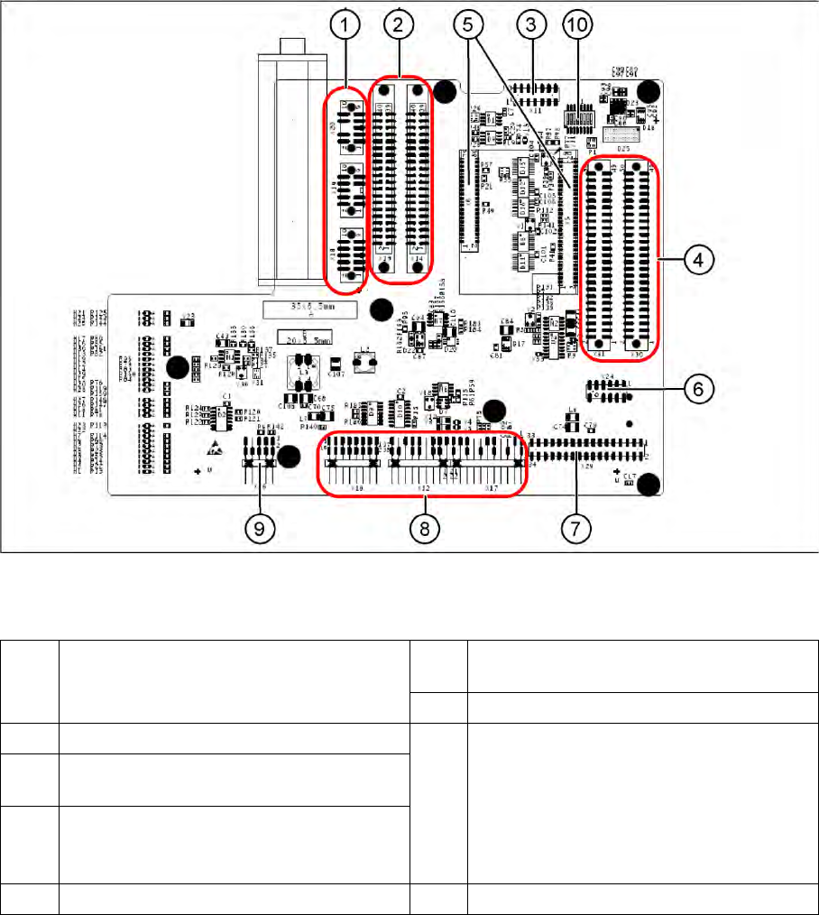
6-4: Gantry head distributor (from above)
Legend
1 X20 stepping motor for reject position
X19 stepping motor for pickup/place
X18 stepping motor for swiveling in the DP axis
6 X24 Test connector for „digital track signals for
X-axis“
7 X29 connector for Vision board
2 X13/X14 flat ribbon cable to C&P head 8 X10 Connector vacuum measurement board
X12 DP axis motor
X16 Reference proximity switch (nor used)
X17 X-axis end position proximity switch (not
used)
X22 Temperature feeler
X21 Free (not used)
3 X11 test connector for CAN Bus, SPI Bus,
RS232
4 X30/X31 flat ribbon cable to P&P head for D1
(D4 not in use)
5 X5/X6 connector for 16 bit processor (TQM) 9 X26 connector for CO sensor
Settings
Description of the PCB boards on the Gantry Gantry
Service Manual SIPLACE D4
217
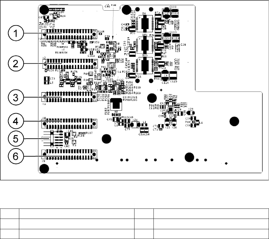
6-5: Gantry head distributor (from below)
Legend
See also:
J
6.3.2.1 8-fold DIP Switch of the gantry head distributor (incl. switch S1) – C&P6/12 [
J
222]
J
6.2.4.1 DIP Switch on Gantry Head Distributor [
J
220]
1 X1 flat ribbon cable 4 X4 not connected
2 X2 flat ribbon cable 5 X15 connector for X-axis track signals
3 X3 flat ribbon cable 6 X9 flat ribbon cable
Settings
Gantry Description of the PCB boards on the Gantry
218 Service Manual SIPLACE D4
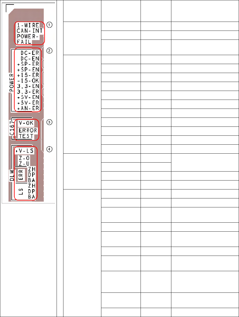
Description of LEDs on the Gantry Head Distributor
SM = stepping motor
Legend PCB labeling LEDS for
oeprating
states
Description
1
CAN Bus
1-WIRE Not in use
CAN-INT OFF not used
POWER-FAIL OFF Error +24 V power supply (from
the main machine)
2
Status voltage
supplies
DC-ER OFF Error DC/DC converter
DC-EN ON Enable DC/DC converter
+SP-ER OFF Error +5V track encoder
+SP-EN ON Enable +5V track encoder
+15-ER OFF Error +15V
-15-OK ON -15V is OK
3.3-EN ON Enable +3.3V digital
3.3-ER OFF Error +3.3V digital
+5V-EN ON Enable +5 V digital
+5V-ER OFF Error +5V digital
+AN-ER OFF Error analog supply C167
3
Head CAN
processor
V-OK ON Internal voltage monitoring of
eSW
V-OK OFF
ERROR OFF Error eSW
TEST Flashing Timer eSW in operation
4
C&P head
functions and
signals
+V-LS ON OK + 15V light barrier
+V-LS OFF Error +15V light barrier
Z-O ON Z axis is not up (in fork light
barrier)
Z-U ON Z down has switched
ERR-ZH OFF Overload SM valve positioning
drive for pickup and place
ERR-DP OFF Overload SM swivel in DP axis
ERR-BA OFF Overload SM valve positioning
drive for reject
LS-ZH ON Light barrier SM valve
positioning drive for pickup and
place
LS-DP ON Light barrier SM for swivel in
DP axis
LS-BA ON Light barrier SM reject