00195166-0402_SM_D4_EN.pdf - 第49页
Service W ork Measuring Voltages on the Power Supply Unit Electrical System Service Manual SIPLACE D4 49 4 Service W ork See also: J 2.2 Preparations for Service Work [ J 16] 4.1 Electrical System 4.1.1 Measuring V olt…
Overview
Pneumatic Unit Overview of Pneumatic Unit
48 Service Manual SIPLACE D4
3.7 Pneumatic Unit
3.7.1 Overview of Pneumatic Unit
The pneumatic unit is a fixed installation inside the machine. The unit is accessible via a door and
contains the complete compressed air supply for all consumer devices.
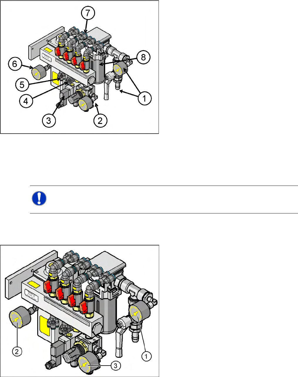
3.7.1.1 Manometer Arrangement
3-31: Pneumatic unit as rack unit (D4)
Legend
1. Main compressed air connection with shutoff
valve and manometer
2. 4x connection for bulkcase feeder with
manometer, manually adjustable (2.5 bar),
location 1-4
3. 4x connection for cutters, location 1 - 4
2x connection for conveyor lifting table
4. 4x connection for nozzle changer
5. 4x connection for docking/undocking the
changeover table
6. Electronic control valve for incoming pressure
manometer.
7. 4x connection for gantries 1 - 4, vacuum
generation C&P head with shutoff valves
8. Compressed air filter (you may need a special
tool to open this)
NOTE: Different pressure
Observe the different pressure for the nozzle changer on the D4 machine (5.1 +/- 0.1 bar),
which is significantly higher than that for the nozzle changer of the D1/D2 machines.
3-32: Main pneumatic unit: manometer arrangement (D4)
Legend
1. Manometer input pressure (5 – 10 bar)
2. Manometer regulated supply pressure 5.0
+0.1 bar for placement heads
3. Manometer for reduced pressure 2.5 +/0.5 bar
(manually adjustable)

Service Work
Measuring Voltages on the Power Supply Unit Electrical System
Service Manual SIPLACE D4
49
4 Service Work
See also:
J
2.2 Preparations for Service Work [
J
16]
4.1 Electrical System
4.1.1 Measuring Voltages on the Power Supply Unit
4.1.1.1 Safety Instructions
4.1.1.2 Tools and equipment required
Digital voltmeter, class 1.5
Measurement range:
– AC voltage: 750 V
– Alternating current: 40 A
– DC voltage: 300 V
– Direct current: 30 A
– Resistance: 200 Ohm - 20 MOhm
Test cable with test probes or terminals
Circuit diagram folder SIPLACE D4 [00194752-xx]
DIN 911 Allen key, size 6
3 mm key, double-bit, DIN 43668-J33 (00304191-xx)
WARNING: Nonobservance of these safety instructions may cause injury to personnel
and damage to the machine!
The service work described in this manual may only be performed by specially trained service
technicians, with appropriate qualifications and expertise.
X Please observe the safety instructions in the Operating Manual for all service work!
DANGER: The machine is supplied with 3 x 400 V~ (or 3 x 204 V~ / 3 x 230 V~ / 3 x 380 V~
/ 3 x 415 V~) ± 5 %, 50/60 Hz mains voltage.
Consequently, parts of the system carry potentially lethal voltages, even when it is switched off
at the main switch.
Incorrect handling of the machine can therefore result in death, severe injury or considerable
damage to equipment.
Measurements and repairs must always be carried out by appropriately qualified personnel.
X Always follow the safety instructions in chapter 2 of this manual.
X Always follow the applicable accident prevention and VDE regulations (particularly DIN EN
60 204 part 1) or the regulations specific to your country.
X Before starting any repairs, switch off at the main switch and disconnect the machine from
the main power supply.
X Secure the system to prevent it being switched on again. If these instructions are not followed,
you may be able to touch live parts, which could result in death or severe injury.
Service Work
Electrical System Measuring Voltages on the Power Supply Unit
50 Service Manual SIPLACE D4
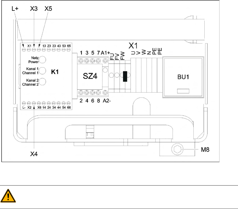
4.1.1.3 Preparing the power supply unit for measurement
The power supply unit and main switch are located in the machine base. In front of the unit there is a set
of safety doors which can be opened with the double-bit key.
The unit is fixed to the machine base using an M8 hexagon socket-head screw.
To measure the power supply, proceed as follows:
X Switch the placement system off at the main switch.
X Open the safety doors with the double-bit key.
X Loosen the M8 lock screw, fastening the underside of the unit at the front (see fig).
4-1: M8 hexagon socket-head screw to lock the unit
X Pull the unit out as far as the stop.
4.1.1.4 What To Do After Completing Service Work
X Fit the power supply unit and fix in place with the M8 hexagon socket-head screw.
X Make sure that you do not pinch the cable when inserting the board!
X Lock the safety doors.
X Remove the key and keep in a safe place.
X Switch the placement system on at the main switch and start it up.
WARNING:
Make sure that the main power cable and supply cables in the machine are not trapped and that
the insulation is not damaged.