00195166-0402_SM_D4_EN.pdf - 第31页
Overview Computer Unit Electrical System Service Manual SIPLACE D4 31 3.2.4 Computer Unit 3-14: Computer unit Legend 3.2.4.1 Overview of Settings 1 Control computer [0302341-xx] 4 Video multicoupler [030 40316-xx] 2 Mach…

Overview
Electrical System Distributors in Sectors 1-4
30 Service Manual SIPLACE D4
3.2.3.5 Overview of Settings
Description Setting Settings
Vision DC/DC converter replaced No settings required
CAN Bus board - CO table terminator replaced Configuration of DIP switch
See
section (3.2.3
Distributors in Sec-
tors 1-4
J
26 )
Fine fuse 5x20 MT 3.15 A replaced No settings required
Relay RS30 24 V replaced No settings required
CAN interface replaced Configuration of DIP switch
See
section (3.2.3
Distributors in Sec-
tors 1-4
J
26 )
CAN I/O module 2 replaced Configuration of DIP switch
See
section (3.2.3
Distributors in Sec-
tors 1-4
J
26 )
Resistor R1 replaced No settings required
Overview
Computer Unit Electrical System
Service Manual SIPLACE D4
31
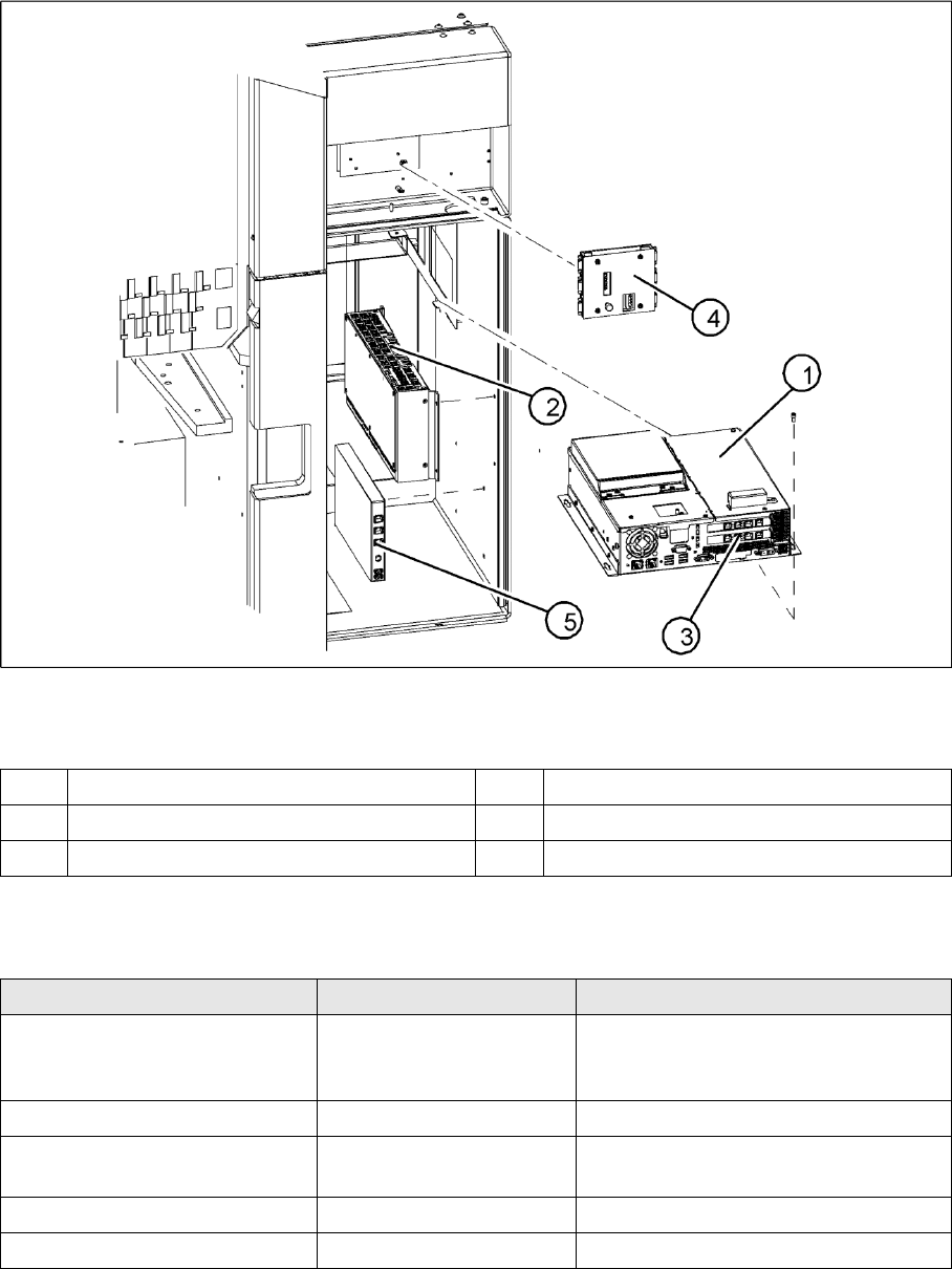
3.2.4 Computer Unit
3-14: Computer unit
Legend
3.2.4.1 Overview of Settings
1 Control computer [0302341-xx] 4 Video multicoupler [03040316-xx]
2 Machine controller [03047697-01] 5 USB hub 2.0 [03032344-01]
3 Hotlink interface [03032343-xx]
Description Setting Comments
Control computer replaced No settings required Backup of machine data
Install software according to respective
installation guide.
Video multiplexer replaced No settings required
Hotlink interface replaced No settings required Make sure that card engages correctly in
the slot.
USB hub 2.0 replaced No settings required
Machine controller replaced No settings required
Overview
Electrical System Axis Unit
32 Service Manual SIPLACE D4
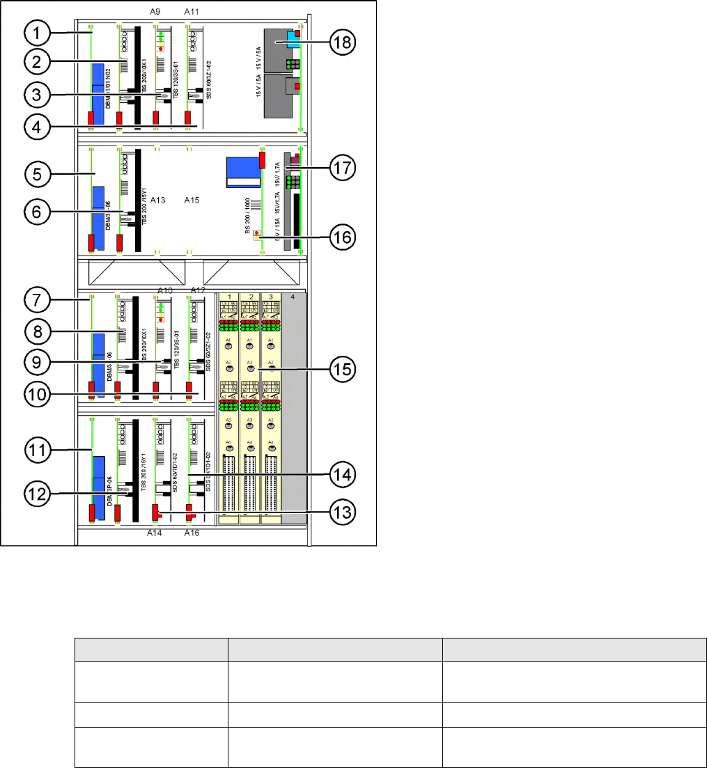
3.2.5 Axis Unit
3.2.5.1 Overview of Settings
3-15: Axis unit location 1/4
Legend
1. X-axis brake board (gantry 1/2)
2. X-axis servo card (gantry 1/2)
3. Star axis servo card (gantry 1/2)
4. Z-axis servo card (gantry 1/2)
5. Y-axis brake board (gantry 1/2)
6. Y-axis servo card (gantry 1/2)
7. X-axis brake board (gantry 3/4)
8. X-axis servo card (gantry 3/4)
9. Star axis servo card (gantry 3/4)
10. Z-axis servo card (gantry 3/4)
11. Y-axis brake board (gantry 3/4)
12. Y-axis servo card (gantry 3/4)
13. DP axis servo card (gantry 1/2)
14. DP axis servo card (gantry 3/4)
15. 3 axis cards A364
16. Ballast circuit (only for axis unit at location 2/3)
17. Power supply 5V/15A, 2x15V/5A
18. Power supply 15V/5A
Description Setting Settings
Complete axis unit
replaced
Set the DIP switch for the relevant
location
At placement area 1+4 (OFF/OFF)
At placement area 2+3 (ON/ON)
Axis card A 364 Install firmware for the relevant axis
See
section.
Servo cards No settings required Servo card for the relevant axis has been
preset.