00195166-0402_SM_D4_EN.pdf - 第143页
Service W ork Replacing the Laser Light Barriers for St opper Positions [0037038 5] Modular Co nveyor Service Manual SIPLACE D4 143 Removal/Installation of transmitter mo dule assembly Removal /installation of receiver m…
Service Work
Modular Conveyor Replacing the Laser Light Barriers for Stopper Positions [00370385]
142 Service Manual SIPLACE D4
4.4.17 Replacing the Laser Light Barriers for Stopper Positions [00370385]
Parts
Laser light barrier transmitter module PA1 assembly [00370385-xx]
Laser light barrier transmitter module PA2 assembly [00370386-xx]
Laser light barrier - receiver module PA1 [00365772-xx]
Laser light barrier - receiver module PA2 [00365774-xx]
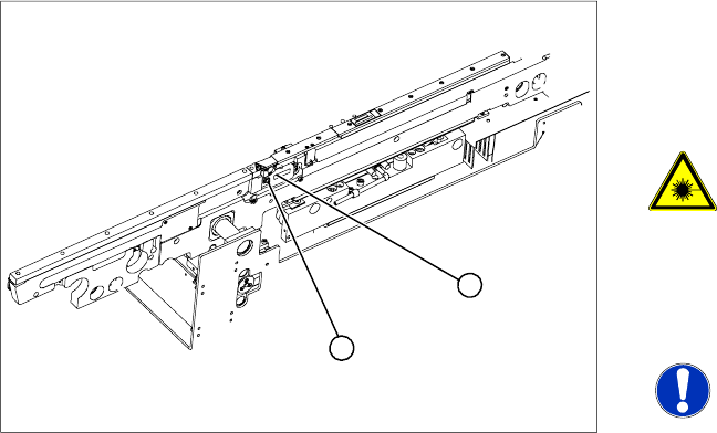
Overview
Legend
1. Transmitter module (amplifier) with 2 screws
2. Transmitter module (round laser diode) with 3
screws
DANGER: The laser light barrier
emits class 2 laser beams (from its
transmitter).
You therefore do not require additional
protective measures!
X Keep your eyes away from the laser
beam!
NOTE:
After setting the laser light barrier you
must check or re-teach the PCB
reference corner!
X Move the PCB conveyor to the position which
gives you best access to the laser light barrier.
X Move the Y gantries into the area outside the
PCB conveyor.
X Switch off the machine and secure it to prevent
unauthorized reactivation.
1
2
Service Work
Replacing the Laser Light Barriers for Stopper Positions [00370385] Modular Conveyor
Service Manual SIPLACE D4
143
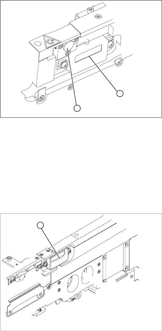
Removal/Installation of transmitter module assembly
Removal /installation of receiver module
X Loosen the 2 fastening screws on the large
transmitter module (1) and the 3 fastening
screws on the small transmitter module (2).
Make sure you do not lose the O-rings.
X Unthread the connection cable as far as the
relevant conversion board of the conveyor
side.
X Unplug the conversion board of the conveyor
side.
X Reconnect the conversion board of the
conveyor side to the power supply and rerun
the connection cable accordingly.
X Fix the new transmitter module in the original
position.
X Make sure that the 3 O-rings are placed on the
3 fastening screws.
X Switch the machine on.
X Move the conveyor system to maximum width.
X Turn the 3 fastening screws to align the
transmitter diode centrally to the receiver. The
entire height of the laser beam must hit the
receiver. Please also refer to the adjustment
instructions.
1
2
X Loosen the 2 screws fastening the receiver
module (1).
X Unthread the connection cable as far as the
relevant conversion board of the conveyor
side.
X Unplug the conversion board of the conveyor
side.
X Reconnect the conversion board of the
conveyor side to the power supply and rerun
the connection cable accordingly.
X Fit the new receiver module in the original
position.
X Switch the machine on.
X Move the conveyor system to maximum width.
X Turn the 2 fastening screws to align the
receiver centrally to the transmitter diode. The
entire height of the transmitter diode laser
beam must hit the receiver. Please also refer
to the adjustment instructions.
1
Service Work
Modular Conveyor Overview of the Electrical Components
144 Service Manual SIPLACE D4
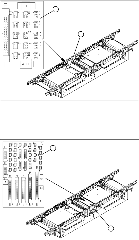
4.4.18 Overview of the Electrical Components
4.4.18.1 Conveyor Side Conversion Board [00359424]
Overview
4.4.18.2 Conveyor Conversion Board [00359425]
Overview
Legend
1. Conveyor side conversion board
2. Cover
The conversion boards for the conveyor sides (1)
are situated on the respective conveyor sides,
under a cover (2).
For terminal assignment details, please refer to
the current version of the circuit diagram folder.
1
2
Legend
1. Conveyor conversion board
2. Cover
The conveyor conversion board (1) is situated in
the vicinity of the intermediate conveyor, under the
cover (2).
For terminal assignment details, please refer to
the current version of the circuit diagram folder.
1
2