00195166-0402_SM_D4_EN.pdf - 第59页
Service W ork Distributors in Sectors 1-4 Electrical System Service Manual SIPLACE D4 59 4.1.3 Distributors in Sectors 1-4 4.1.3.1 Replacing p arts The asse mblies are locate d be hind th e co vers in the r e levant sect…
Service Work
Electrical System Measuring the Power Supply Unit
58 Service Manual SIPLACE D4
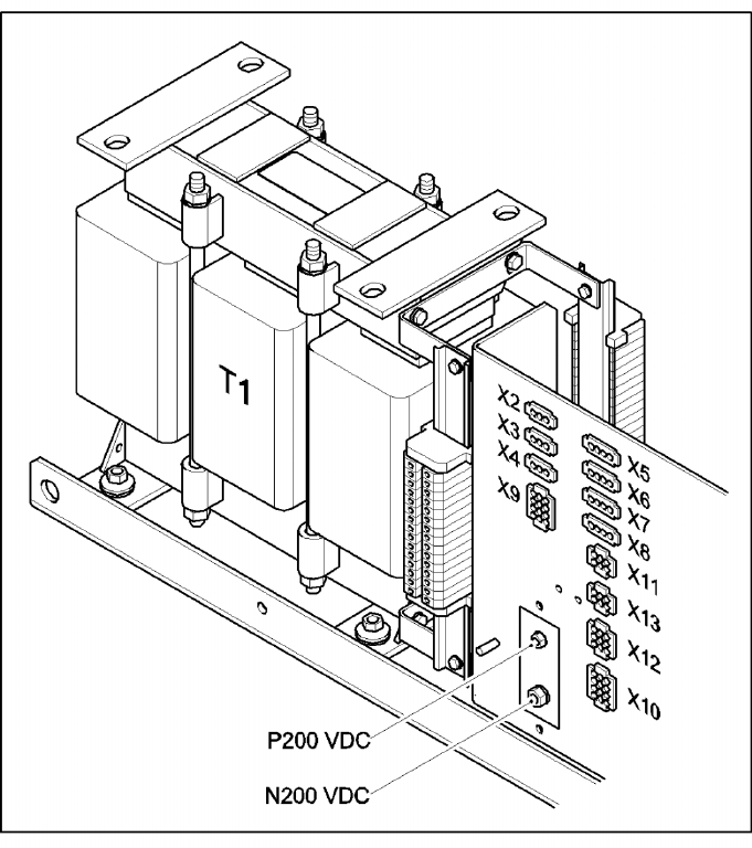
Terminal panel of the power supply unit
4-6: Terminal panel of the power supply unit
The pin assignments of the individual plugs are shown in the detailed circuit diagrams in section 3
"Circuit diagrams".
T1 11.1 kVA three-phase transformer
X14 P200 V - screwed connection M6 (+) for supplying the X/Y axis servo amplifier
X15,16,17, EEP N200 V - screwed connection M8/M6 (-) for supplying the X/Y axis servo amplifier
X2 To the monitor 1, 2
X3 Box PC
X4 Micro Box PC
X5 Main distributor/subdistributor (regulated voltage)
X6 PCB conveyor
X7 Subdistributor (unregulated voltage)
X8 Axis unit 1
X9 Axis unit 2
X10 Main distributor (unregulated voltage)
X12 From/to the main distribution unit, (control signals, power supply)
X13 From/to the main distribution unit, (SSK peripherals)
Service Work
Distributors in Sectors 1-4 Electrical System
Service Manual SIPLACE D4
59
4.1.3 Distributors in Sectors 1-4
4.1.3.1 Replacing parts
The assemblies are located behind the covers in the relevant sectors. The assemblies are fixed to profile
rails and are connected via terminal strips.
X Undo and remove the fastening screws from the relevant cover. Remove the cover.
X Mark the assembly connections for later reference.
X Loosen the assembly connections.
X Lift the assembly off the profile bar. Loosen any fastening screws.
4.1.4 Axis Unit
4.1.4.1 Replacing parts
X End all placement operations with the machine.
X Switch the placement system off at the main switch.
X You can now access the axis unit at the required location (1/4 or 2/3).
Complete Axis Unit
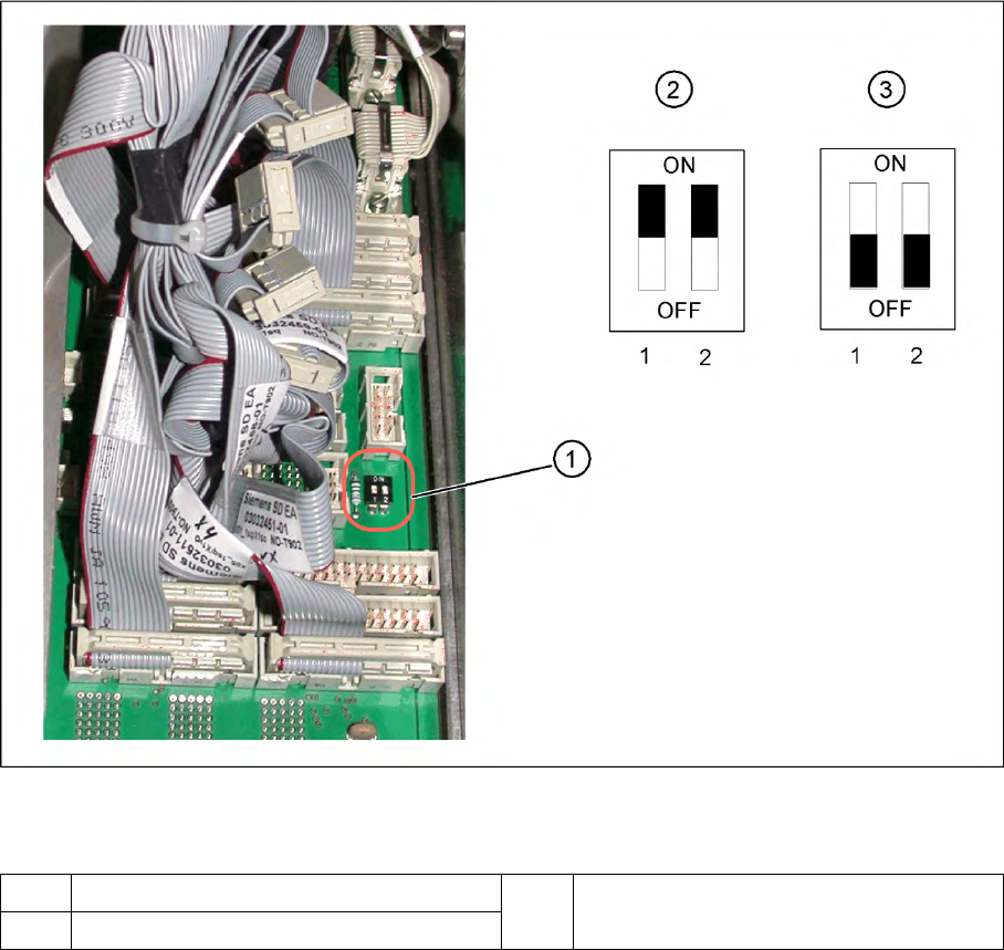
4-7: DIP switch on the backplane
Legend
If the axis unit has been replaced, you will need to configure the axis unit for the relevant installation
position. This involves adjusting the DIP switch on the backplane accordingly.
1 Position of DIP switch on the backplane 3 Setting for axis unit at location 2/3
2 Setting for axis unit at location 1/4
Service Work
Electrical System Axis Unit
60 Service Manual SIPLACE D4
Replacing the A364 Axis Card
X End all placement operations with the machine.
X Switch the placement system off at the main switch.
X You can now access the axis unit at the required location (1/4 or 2/3).
X Loosen the screws holding the relevant axis card.
X Remove the axis card from the unit by moving the release lever up and down.
X Insert the new axis card and push the assembly in (you will feel a slight resistance) until it engages
and then tighten the two fastening screws.
X Switch the machine on again.
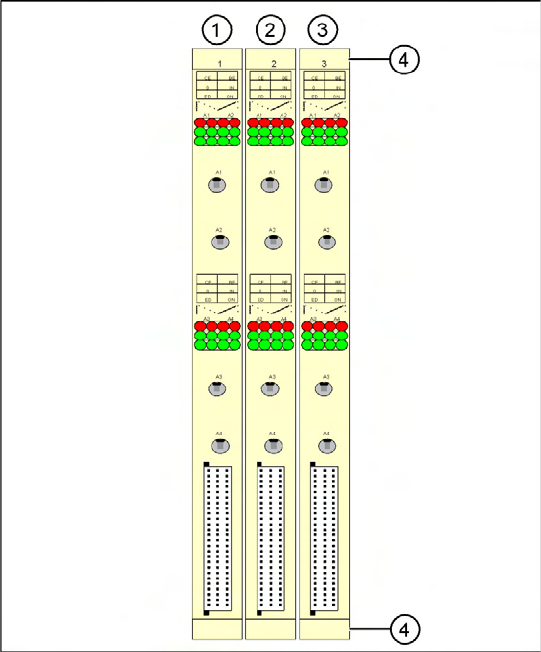
4-8: A364 axis cards on the D2/D4
Legend for D4
Gantry numbers for PA1 (in brackets for PA2)
1. X ,Y , star and Z axis for gantry 1 (2)
2. X ,Y , star and Z axis for gantry 4 (2)
3. DP axis for gantry 1 and 4 (2 and 3)
4. Release lever with screwed connection