00195166-0402_SM_D4_EN.pdf - 第90页
Service Work Component Handling Cutter 90 Serv ice Manual SIPLACE D4 Installing the Cutter X Make sure that the following warning signs ar e on the cover pla te over the moveable blade (see operating manual) a nd, if the…
Service Work
Cutter Component Handling
Service Manual SIPLACE D4
89
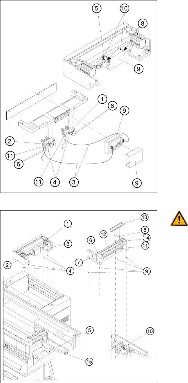
X Remove the cover from the cable duct (5).
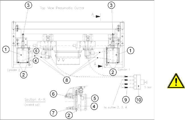
X Disconnect the compressed air connection (9)
(Y socket union) for the cutter in the cable duct
(5).
X Unplug the plug-and-socket connection of the
power supply and the drive on the control
board (see -> 11, 10).
X Carefully undo the corresponding cable tie
(10) on the outside of the control board box.->
Do not damage the cables in this process.
WARNING:
The area under the cutter must be
clear.
X (e.g., do not place your feet under it
either).
X Loosen the screws fastening the cutter to the
machine base
2 M6x25 screws each (4), on the left (2) and
right cutter holders (3).
In exceptional cases, disks or plates may have
been installed between the contact surface of
the cutter on the machine base and the cutter
itself.
-> Save these disks / plates and re-install them
later.
X Securely hold the cutter tight at both ends.
X Pull the cutter out away from the contact
surfaces (on the machine base) towards the
outside of the machine (towards your body).
X Set the cutter down such that it does not pose
a risk of injury to uninvolved personnel either.
Put it in its own crate / container immediately.
Service Work
Component Handling Cutter
90 Service Manual SIPLACE D4
Installing the Cutter
X Make sure that the following warning signs are on the cover plate over the moveable blade (see
operating manual) and, if they are not, attach them:
Adhesive Label with text " Disconnect machine from line voltage and....",
Adhesive Label: Triangle warning symbol "Hand injury".
NOTE:
X If you are installing a new cutter, remove any excess oil or lubrication grease, before
installation.
CAUTION:
X Tighten the screws to the correct
torque.
X If there were disks or plates inserted between
the contact surface of the cutter on the
machine base and the cutter itself, re-install
them now.
The cutter must be shimmed to the same
height at all 4 contact points.
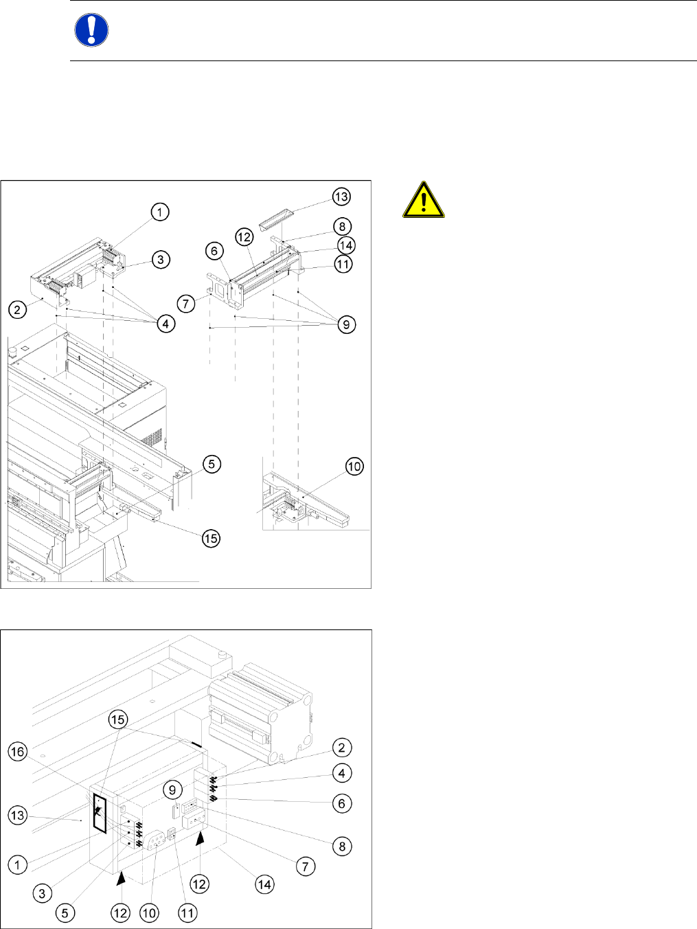
X In the reverse order to disassembly, place the
new pneumatic cutter on the contact surfaces
of the machine base and push it in to the
fixture position.
X To avoid dropping the cutter, insert all 4 M6
screws (4) into the holes now:
X Pull the cutter as far as possible away from the
PCB conveyor for the time being.
X Snug up the screws somewhat for the time
being.
X Remove the cover (14) from the control board
of the new cutter.
X Plug the press-fit connection of the power
supply and the drive into the control board (11,
10).
X Use a cable tie to fasten the cables running to
the cable duct to the fixing pedestal on the
control board box.
Make sure that there is no strain on the cable/
press-fit connections
Service Work
Cutter Component Handling
Service Manual SIPLACE D4
91
See also:
J
Tightening Torques for Cutter Screws [
J
87]
J
6.4.3 Check the gap between the empty-tape baffle, inside and the leading edge of the tape deflector.
[
J
241]
J
4.3.2.4 Overview of Cutter [
J
86]
J
3.4.2.2 Overview: Mechanical Construction [
J
38]
X Plug the compressed air connection to the
machine into the Y socket union (9) (in the
cable duct).
X Place the cover back on the control board and
the cable duct.
X Fit the empty-tape duct assembly and check
the gap between the empty-tape baffle, inside
and the leading edge of the tape deflector.
X In this position tighten all 4 screws crosswise.
CAUTION:
X Tighten the screws to the correct
torque.
X Perform the appropriate “Final Steps”.