00195166-0402_SM_D4_EN.pdf - 第239页
Settings Setting the COT Basic Height Component Handling Service Manual SIPLACE D4 239 6.4.1.3 Adjusting the Component T rolley Height X Screw the eyebolt into the M12 hole provided (1) on the component trolley ta ble. X…
Settings
Component Handling Setting the COT Basic Height
238 Service Manual SIPLACE D4
6.4 Component Handling
6.4.1 Setting the COT Basic Height
6.4.1.1 Tools and Equipment
The following tools and equipment are needed to adjust the height of the component trolley:
Set of Allen keys, size 5
Eyebolt with M12 thread to raise the component trolley table,
DIN 580 M12-St [00048350-xx]
Leverage device for raising the component trolley table, must be able to carry at least 80 kg
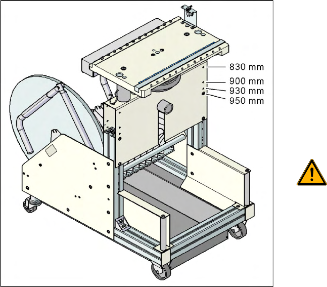
6.4.1.2 Adjusting the Component Trolley to the Board Transport Height
6-22: Component trolley with a PCB conveyor height of 950 mm
Legend
Holes drilled for board transport heights 830 -
950 mm in the guidance bars
The component trolley for the S feeder modules
can be easily and quickly adjusted to the following
board transport heights:
830 mm ±15 mm standard height
900 mm ±15 mm SMEMA height
930 mm ±15 mm SMEMA height
950 mm ±15 mm SMEMA height
WARNING:
The component trolley height may only
be set by SIPLACE technicians or
other qualified and officially authorized
(certified) personnel.
X Observe the applicable accident
prevention regulations.
X Remove all feeder modules from the
changeover table plate, before you
adjust the height of the changeover
table.
Settings
Setting the COT Basic Height Component Handling
Service Manual SIPLACE D4
239
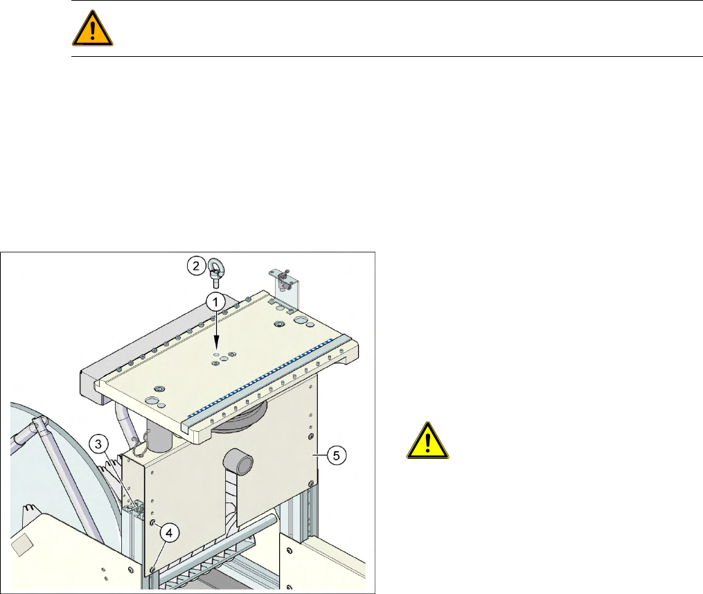
6.4.1.3 Adjusting the Component Trolley Height
X Screw the eyebolt into the M12 hole provided (1) on the component trolley table.
X Hook the leverage device into the eyebolt (2).
X Tighten the rope of the leverage device.
X Loosen the 8 hexagon socket-head screws, M6x12 (4).
X Lift or lower the component trolley table to the required height. Make sure that the hole for the
required height in the bridge (5) is level with the top hole in the vertical profile bar (3).
X Fasten the bridge (5) to the vertical profile bar (3) with the 8 hexagon socket-head screws M6x12 (4).
X Unscrew the eyebolt from the component trolley table.
WARNING:
Lift all feeder modules off the component trolley table plate.
6-23: Position of eyebolt on component trolley
Legend
1. M12 hole drilled for eyebolt
2. Eyebolt DIN 580 M12-St
3. Vertical profile bar
4. 8 x hexagon socket-head screw SN 62355,
M6x12
5. Bridge
CAUTION:
Always use the fit-up aid (screwed
eyelet) to fix the table plate,
irrespective of whether you want to
raise or lower the component trolley.
Settings
Component Handling Tape Cutter Control Unit
240 Service Manual SIPLACE D4
6.4.2 Tape Cutter Control Unit
The jumper for the CAN bus addressing must be set according to the corresponding location in the
machine.
NOTE: Control unit [03006411-xx] is replaced by CAN node module.
This version is replaced by the backwards compatible CAN node [03052027-xx] module.
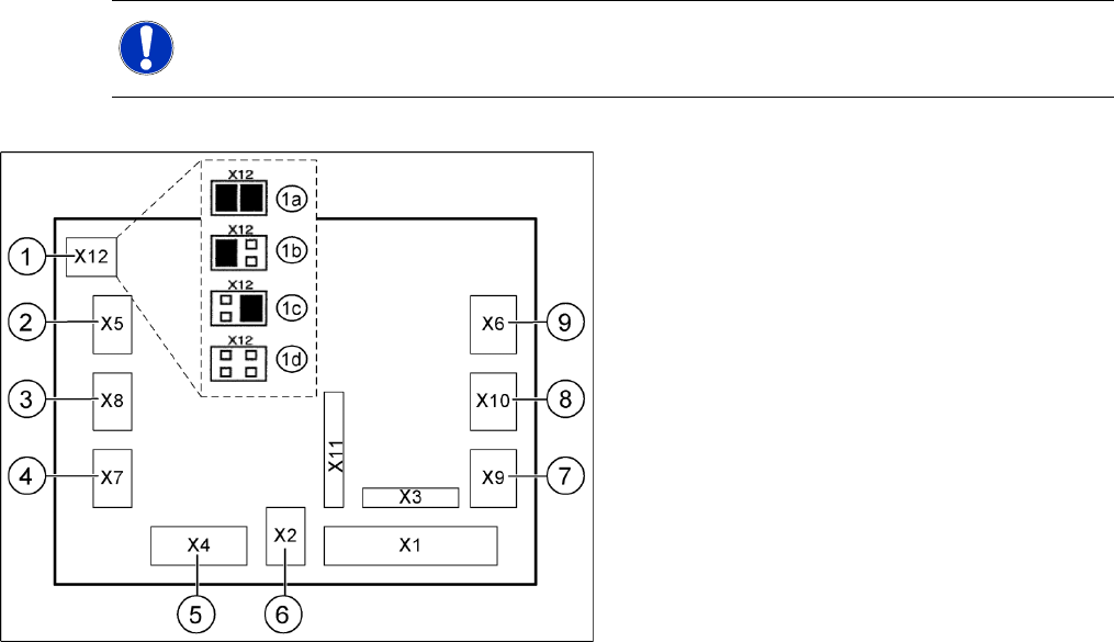
6-24: Jumper setting on the tape cutter unit (example of D4 shown)
Legend
1. X12 – Jumper for location code of cutter:
1a: Gantry 1
1b: Gantry 2
1c: Gantry 3
1d: Gantry 4
2. X5 – Voltage supply to valve (left)
3. X8 – Proximity switch for stroke cylinder out
(left)
4. X7 – Proximity switch for stroke cylinder in
(left)
5. X4 – CAN bus connection
6. X2 – Voltage supply for cutter +24 V and +5 V
7. X9 – Proximity switch for stroke cylinder in
(left)
8. X10 – Proximity switch for stroke cylinder out
(right)
9. X6 – Voltage supply to valve (right)