00195166-0402_SM_D4_EN.pdf - 第8页
Table of contents 8 Serv ice Manual SIPLACE D4 6.4.2 Tape Cutter Control U nit .......... ................. ............ ............. ............. ................ ............. .... ................... 240 6.4.3 Check…
Table of contents
Service Manual SIPLACE D4
7
5.8 Location Tester................................................................................................................................. 208
5.9 Z End Stopper Star Gauge for C&P6/12 [03019865-01]................................................................. 208
5.10 Adjustment Aid for C&P DLM [00327005-01].................................................................................. 209
5.11 Calibration Tool [03010565-01]........................................................................................................ 210
5.12 Calibration Nozzle for Twin Head [03008862-xx] ........................................................................... 210
6 Settings. . . . . . . . . . . . . . . . . . . . . . . . . . . . . . . . . . . . . . . . . . . . . . . . . . . . . . . . . . . .211
6.1 Electrical System.............................................................................................................................. 211
6.1.1 Checking the Firmware Function ........................................................................................................ 211
6.1.2 Firmware Download Note ................................................................................................................... 211
6.2 Gantry ................................................................................................................................................ 212
6.2.1 Travel Ranges and Speed Monitoring (A364)..................................................................................... 212
6.2.2 Anticrash Function for the A364 Axis Card ......................................................................................... 213
6.2.2.1 Anticrash Function for the A364 ....................................................................................................... 213
6.2.2.2 Anticrash Monitoring for the A364 .................................................................................................... 214
6.2.2.3 Error "Gantry Crash" ......................................................................................................................... 214
6.2.2.4 Count Error: ...................................................................................................................................... 214
6.2.2.5 Anticrash Function - Procedure ........................................................................................................ 215
6.2.3 Description of the PCB boards on the Gantry..................................................................................... 216
6.2.3.1 Gantry Head Distributor .................................................................................................................... 216
6.2.3.2 Vision Board (Digital) ........................................................................................................................ 219
6.2.3.3 CAN 16 bit processor board (TQ module) ........................................................................................ 219
6.2.4 Checking the DIP Switches................................................................................................................. 220
6.2.4.1 DIP Switch on Gantry Head Distributor............................................................................................. 220
6.2.4.2 DIP Switch on Vision Board.............................................................................................................. 220
6.2.5 Mechanical Adjustment of the Incremental Encoder........................................................................... 220
6.3 C&P12 ................................................................................................................................................ 221
6.3.1 Calibrating the C&P Head and Cameras ............................................................................................ 221
6.3.2 Boards at C&P12 ................................................................................................................................ 222
6.3.2.1 8-fold DIP Switch of the gantry head distributor (incl. switch S1) – C&P6/12 ................................... 222
6.3.2.2 LEDs on gantry head distributor ....................................................................................................... 223
6.3.2.3 SP_12 Digital Intermediate Distributor [00330648-05]...................................................................... 223
6.3.3 Overview of Settings on the C&P6/12................................................................................................. 225
6.3.4 Setting the Resolution on the Star Axis .............................................................................................. 226
6.3.5 Setting the Digital Rotary Encoder for the DP Axis............................................................................. 226
6.3.6 Setting the Z axis Belt Tension ........................................................................................................... 227
6.3.7 Adjusting the Stop for the Z Axis......................................................................................................... 227
6.3.7.1 Tools and Equipment ........................................................................................................................ 227
6.3.7.2 General ............................................................................................................................................. 228
6.3.7.3 Settings ............................................................................................................................................. 228
6.3.8 Setting the Light Barrier Down ............................................................................................................ 229
6.3.9 Determining the Zero Point Correction for the Star Axis of the C&P Head......................................... 230
6.3.10 Setting the Mechanical Position of the Valve Positioning Drives ........................................................ 231
6.3.11 Adjustment of air pressure values....................................................................................................... 232
6.3.11.1 Tools and Equipment ........................................................................................................................ 232
6.3.11.2 Setting the Air Blast Pressure Values ............................................................................................... 232
6.3.11.3 Setting the Air Blast Pressure Values with the Compressed Air Testing Device .............................. 233
6.3.12 Performing a Vacuum Test on the C&P 6/12 DLM Heads.................................................................. 234
6.3.13 Other Mechanical Settings on the Star ............................................................................................... 237
6.4 Component Handling........................................................................................................................ 238
6.4.1 Setting the COT Basic Height ..............................................................................................
............... 238
6.4.1.1 Tools
and Equipment........................................................................................................................ 238
6.4.1.2 Adjusting the Component Trolley to the Board Transport Height ..................................................... 238
6.4.1.3 Adjusting the Component Trolley Height .......................................................................................... 239
Table of contents
8 Service Manual SIPLACE D4
6.4.2 Tape Cutter Control Unit ..................................................................................................................... 240
6.4.3 Check the gap between the empty-tape baffle, inside and the leading edge of the tape deflector..... 241
6.5 Conveyor............................................................................................................................................242
6.5.1 Adjusting the Tension of the Conveyor Toothed Belt.......................................................................... 242
6.5.1.1 Measuring Points and Belt Tensions for D4 Conveyor ..................................................................... 244
6.5.2 Setting the fixed conveyor side (single and dual conveyor) ................................................................ 245
6.5.2.1 General Notes ................................................................................................................................... 245
6.5.2.2 Widening the Conveyor (Flexible Dual Conveyor for Single Conveyor Mode).................................. 246
6.5.2.3 Connecting the Dual Conveyor Lifting Tables................................................................................... 247
6.5.2.4 Converting the Single Conveyor Mode Back to Flexible Dual Conveyor Mode ................................ 247
6.5.3 Moving the Fixed Conveyor Edge for ’Extra Wide Conveyor’ ............................................................. 248
6.5.4 Checking the Limit Switch Position ..................................................................................................... 249
6.5.4.1 Adjusting the Limit Switch for Initializing the Adjustment Unit........................................................... 250
6.5.5 Width Adjustment Unit......................................................................................................................... 250
6.5.5.1 Setting the Proximity Switch on the Adjustment Unit ........................................................................ 250
6.5.5.2 Setting the Pneumatic Cylinder Proximity Switch on the Adjustment Unit ........................................ 251
6.5.6 Setting the Laser Light Barrier for the Stopper Position...................................................................... 251
6.5.7 Function "Constant Transport Time in Placement Area"..................................................................... 253
6.5.8 Light Barrier Functions in Input, Intermediate and Output Conveyors ................................................ 254
6.5.9 Setting the Clamping Actuator ............................................................................................................ 254
6.5.10 Board Clamping Functions.................................................................................................................. 255
6.5.10.1 Setting Board Clamping .................................................................................................................... 256
6.5.11 Lifting Table Functions ........................................................................................................................ 257
6.5.11.1 Adjusting the Speed of the Lifting Table (from SW 602) ................................................................... 257
6.5.11.2 Setting the Lifting Table Unit [00358684-05]..................................................................................... 259
6.5.12 Conveyor Control TSP 301 ................................................................................................................. 259
6.5.12.1 Jumper Settings for TSP 301 ............................................................................................................ 259
6.5.12.2 Conveyor Control TSP 301 with Siemens Interface.......................................................................... 261
6.5.12.3 LED Display on Conveyor Control TSP 301 ..................................................................................... 262
6.5.12.4 Assignment Table: LEDs on the TSP 301 Conveyor Control............................................................ 262
6.5.12.5 Siemens/SMEMA TSP 301 Interface Description .............................................................................266
Introduction
Serial Number of D4 Module Safety Instructions
Service Manual SIPLACE D4
9
1Introduction
This service guide is a manual or reference work for performing service work on the SIPLACE® D4
placement machines.
1.1 Safety Instructions
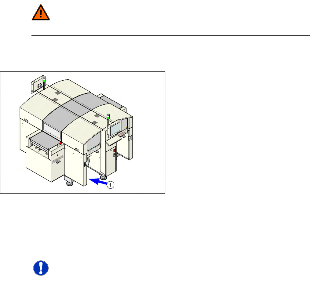
1.1.1 Serial Number of D4 Module
1.1.2 Environmentally-Friendly Disposal of Materials and Components
SIPLACE products are manufactured using only materials and parts that can be easily separated and
disposed of in an environmentally-friendly way. Hazardous materials are not necessary for the
installation, dismantling or operation of the machine.
1.1.3 Use of Original SIPLACE Accessories and Spare Parts
Only use S,3/$&( original spare parts and authorized accessories. The use of other parts will affect
safety and will invalidate the liability for any consequential damage.
DANGER: Nonobservance of these safety instructions may cause injury to personnel and
damage to the machine!
X Please observe the safety instructions in the operating manual of the according machine for
all service work!
The serial number of your placement machine can
be found on the typeplate (1).
NOTE:
The company operating the system has sole responsibility for the proper, environmentally-
friendly disposal of machines, working materials, consumables and wear parts.
X Please observe your national statutory provisions for waste disposal and environmental
protection.