00195166-0402_SM_D4_EN.pdf - 第131页
Service W ork Replacing the Stepping Motor of the Width Adjustment System [00367174] Modular Conveyor Service Manual SIPLACE D4 131 4.4.1 1 Replacing the Steppi ng Motor of the Wid th Adju stment System [00367174] Overvi…
Service Work
Modular Conveyor Replacing the Lifting Table Stabilizer (Stabilizer Unit) [00358684-xx]
130 Service Manual SIPLACE D4
Removal
Installation and adjustment
X Move the PCB conveyor to the position which
gives you best access to the lifting table.
X Move the Y gantries into the area outside the
PCB conveyor.
X Switch off the machine and secure it to prevent
unauthorized reactivation.
X Loosen the screws fastening the lifting table
plate and remove the lifting table plate from the
lifting table unit.
X Loosen the two screws (3) holding the
stabilizer (5).
X Undo the locknut (2) and take the stabilizer by
its handle (4), twisting it out of the mounting
block.
X Insert and twist the new stabilizer (5) until the
plunger just touches the actuator (1), so that
the lifting table can be gently moved upwards.
X Use a torque wrench:
Secure this position with the locknut (2)
tightened to 8Nm.
X Check whether the stabilizer has been fixed
onto the mounting block with the locknut and
that the stabilizer plunger has a gap of approx.
0.1 mm to the actuator (gap in untriggered
mode). In this default setting, the lifting table
should move up gently.
X If this is not the case, loosen the locknut and
turn the stabilizer approx. one rotation into the
mounting block.
X Fit the lifting table plate.
X Start SITEST and move the lifting table up.
X The lifting table should move up gently i.e. you
should not hear the PCB clamping device
audibly locking into place and no clamping
device error messages should be issued.
X Check the speed of the lifting table cylinder
and correct where necessary.
Service Work
Replacing the Stepping Motor of the Width Adjustment System [00367174] Modular Conveyor
Service Manual SIPLACE D4
131
4.4.11 Replacing the Stepping Motor of the Width Adjustment System [00367174]
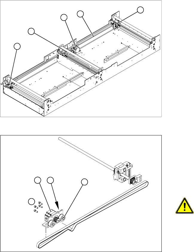
Overview
Legend
1. Width adjustment stepping motor
2. Toothed belt for the drive
3. Adjustment units 1, 2 and 3
3
3
1
3
2
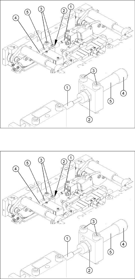
Legend
1. Loosening the eccentric axle on the deflection
pulley
2. Locknut on the eccentric axle
3. Fastening screws for stepping motor
4. Stepping motor
ATTENTION: Do not damage the
toothed belt!
During the following removal and
installation of the motor, the toothed
belt for the width adjustment drive must
not be stretched or kinked!
X Move the PCB conveyor to the position which
gives you best access to the stepping motor of
the width adjustment system.
X Move the Y gantries into the area outside the
PCB conveyor.
X Switch off the machine and secure it to prevent
unauthorized reactivation.
4
1
3
2
Service Work
Modular Conveyor Replacing the Stepping Motor of the Width Adjustment System [00367174]
132 Service Manual SIPLACE D4
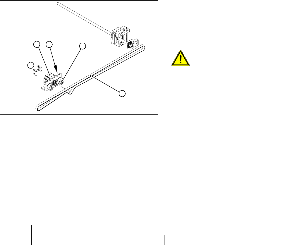
Removal/Installation
See also:
J
6.5.1 Adjusting the Tension of the Conveyor Toothed Belt [
J
242]
X Loosen the screws fastening the lifting table
plate and remove the lifting table plate from the
lifting table unit.
X Loosen the eccentric axis (1) on the deflection
pulley and relieve the tension on the drive
toothed belt (5).
ATTENTION: Toothed belt must not
come off!
When relaxing the toothed belt, make
sure the belt does not come off (skip)
the toothed disks at the 3 adjustment
units. This would cause incorrect
alignment of the adjustment units.
Secure these positions with a suitable
tool (screw clamp etc.)
X Remove the 4 fastening screws (3) and then
lift out the stepping motor (4).
X Unplug the connection cable in the cable duct.
X Fit the new stepping motor and reconnect the
system to the electrical system.
X Tension the drive toothed belt.
Position the measuring point of the belt
tension device at the strand center (i.e. the
longest distance between two toothed disks)
of the conveyor toothed belt.
X Set the tension of the drive toothed belt
according to the following values.
4
5
1
3
2
Belt tension - width adjustment
Toothed belt for the drive 24 Hz +/- 2 Hz