00195166-0402_SM_D4_EN.pdf - 第237页
Settings Other Mechanical Settings on the Sta r C&P12 Service Manual SIPLACE D4 237 Maintenance recommendations: Use the valve plunger ONLY when grease d. (Isoflex topas). Replacing the va lve plunger also means:…
Settings
C&P12 Performing a Vacuum Test on the C&P 6/12 DLM Heads
236 Service Manual SIPLACE D4
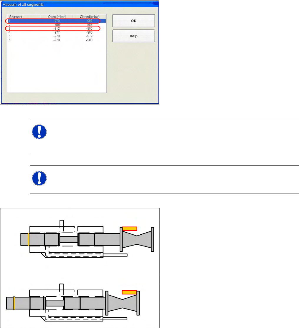
Scenario 2
Example of defective vacuum values, which
indicate a damaged silicone hose on segment 1
and an open nozzle at segment 3.
NOTE: Silicone hose defect
Under certain circumstances, silicone hose defects might only be detected when the segments
are moved out. It could therefore be advisable to release the Z axis and to perform a vacuum
test of the segment in its lowered state (single measurement run).
NOTE: Missing valve plunger
If both measurements for a particular segment are only around 210mbar, this indicates that the
valve plunger is missing.
Vacuum values and valve plunger
positions
If the valve plunger is in the position "nozzle
open", the vacuum area will be sealed against
the environment with two seals.
If the valve plunger is in the position "nozzle
closed", the vacuum area (at the rear, near the
drive) will be sealed against the environment
with only one seal.
If the "vacuum value closed" is too low, this
indicates that the seal is not sufficiently greased or
that it is damaged.
Settings
Other Mechanical Settings on the Star C&P12
Service Manual SIPLACE D4
237
Maintenance recommendations:
Use the valve plunger ONLY when greased. (Isoflex topas).
Replacing the valve plunger also means:
– Clean the valve plunger housing! Otherwise good plungers with new grease are installed in the
old, contaminated environment.
– Grease the valve plunger: Use the appropriate tool [03049689-01] to grease the valve plunger.
– Perform vacuum tests with the red SOKO nozzles, vacuum test DLM [03067029-01].
Regularly check the sleeve-nozzle vacuum plate "blue" (available from 10/2008, white) and replace
when necessary (with 1.5mm Allen key).
6.3.13 Other Mechanical Settings on the Star
Set the air blast tube so that it overlaps the circular guide frame by 0.7 mm.
Settings
Component Handling Setting the COT Basic Height
238 Service Manual SIPLACE D4
6.4 Component Handling
6.4.1 Setting the COT Basic Height
6.4.1.1 Tools and Equipment
The following tools and equipment are needed to adjust the height of the component trolley:
Set of Allen keys, size 5
Eyebolt with M12 thread to raise the component trolley table,
DIN 580 M12-St [00048350-xx]
Leverage device for raising the component trolley table, must be able to carry at least 80 kg
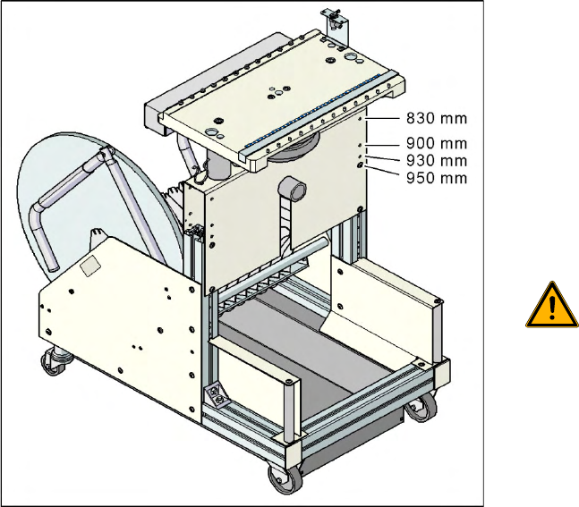
6.4.1.2 Adjusting the Component Trolley to the Board Transport Height
6-22: Component trolley with a PCB conveyor height of 950 mm
Legend
Holes drilled for board transport heights 830 -
950 mm in the guidance bars
The component trolley for the S feeder modules
can be easily and quickly adjusted to the following
board transport heights:
830 mm ±15 mm standard height
900 mm ±15 mm SMEMA height
930 mm ±15 mm SMEMA height
950 mm ±15 mm SMEMA height
WARNING:
The component trolley height may only
be set by SIPLACE technicians or
other qualified and officially authorized
(certified) personnel.
X Observe the applicable accident
prevention regulations.
X Remove all feeder modules from the
changeover table plate, before you
adjust the height of the changeover
table.