00195166-0402_SM_D4_EN.pdf - 第32页
Overview Electrical System Axis Unit 32 Serv ice Manual SIPLACE D4 3.2.5 Axis Unit 3.2.5.1 Overview of Settings 3-15: Axis unit location 1/4 Legend 1. X-axis brake board (gantry 1/2) 2. X-axis servo card (gantry 1/2) 3. …
Overview
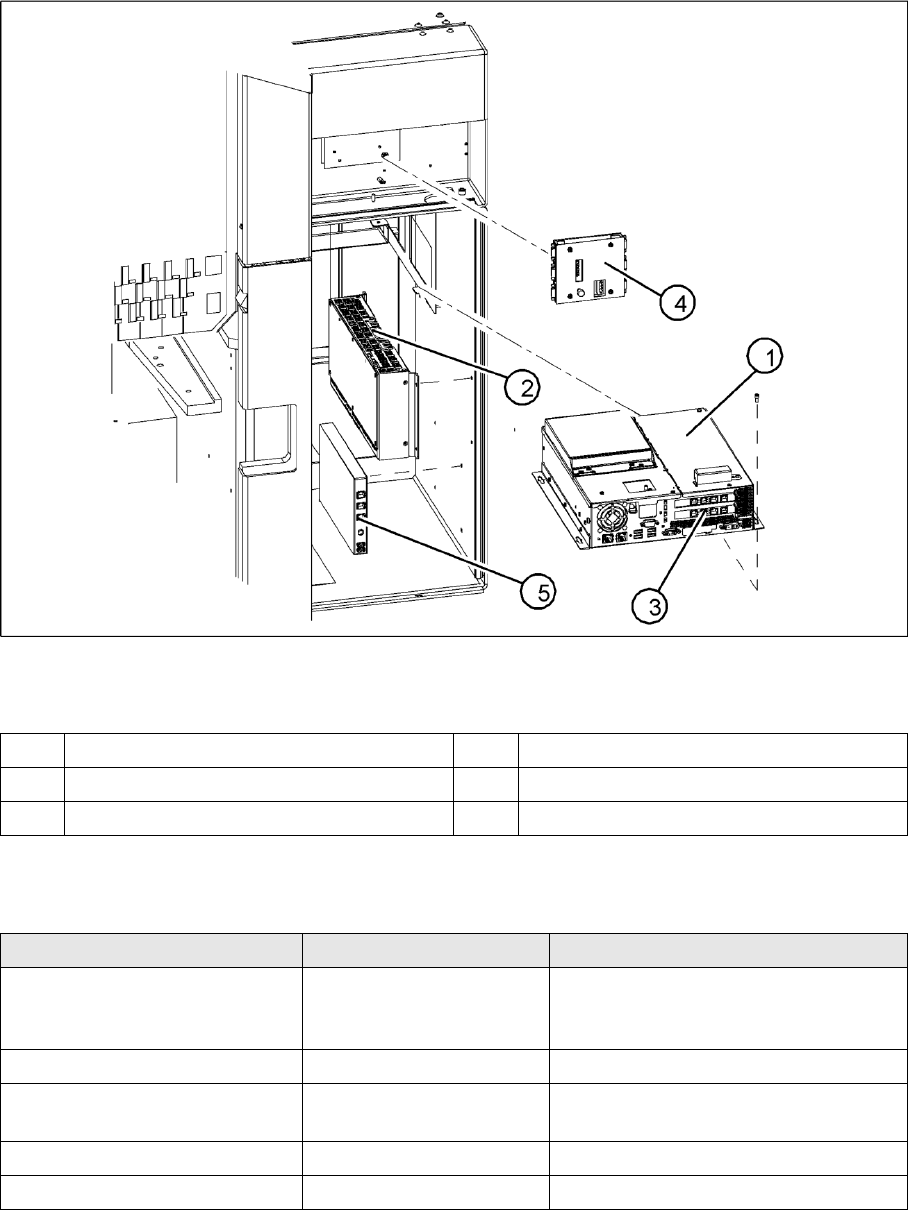
Computer Unit Electrical System
Service Manual SIPLACE D4
31
3.2.4 Computer Unit
3-14: Computer unit
Legend
3.2.4.1 Overview of Settings
1 Control computer [0302341-xx] 4 Video multicoupler [03040316-xx]
2 Machine controller [03047697-01] 5 USB hub 2.0 [03032344-01]
3 Hotlink interface [03032343-xx]
Description Setting Comments
Control computer replaced No settings required Backup of machine data
Install software according to respective
installation guide.
Video multiplexer replaced No settings required
Hotlink interface replaced No settings required Make sure that card engages correctly in
the slot.
USB hub 2.0 replaced No settings required
Machine controller replaced No settings required
Overview
Electrical System Axis Unit
32 Service Manual SIPLACE D4
3.2.5 Axis Unit
3.2.5.1 Overview of Settings
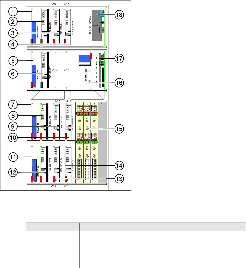
3-15: Axis unit location 1/4
Legend
1. X-axis brake board (gantry 1/2)
2. X-axis servo card (gantry 1/2)
3. Star axis servo card (gantry 1/2)
4. Z-axis servo card (gantry 1/2)
5. Y-axis brake board (gantry 1/2)
6. Y-axis servo card (gantry 1/2)
7. X-axis brake board (gantry 3/4)
8. X-axis servo card (gantry 3/4)
9. Star axis servo card (gantry 3/4)
10. Z-axis servo card (gantry 3/4)
11. Y-axis brake board (gantry 3/4)
12. Y-axis servo card (gantry 3/4)
13. DP axis servo card (gantry 1/2)
14. DP axis servo card (gantry 3/4)
15. 3 axis cards A364
16. Ballast circuit (only for axis unit at location 2/3)
17. Power supply 5V/15A, 2x15V/5A
18. Power supply 15V/5A
Description Setting Settings
Complete axis unit
replaced
Set the DIP switch for the relevant
location
At placement area 1+4 (OFF/OFF)
At placement area 2+3 (ON/ON)
Axis card A 364 Install firmware for the relevant axis
See
section.
Servo cards No settings required Servo card for the relevant axis has been
preset.
Overview
Axis Unit Gantry
Service Manual SIPLACE D4
33
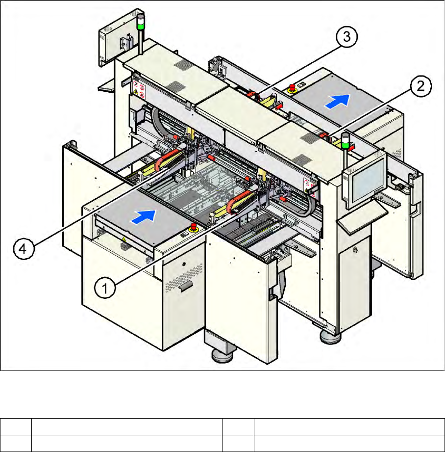
3.3 Gantry
The placement system is equipped with four gantries. These enable the four collect&place heads to be
positioned in the x and y directions with great accuracy and independently of one another.
3-16: Gantries on the placement system
Legend
The structure of the gantries makes them very torsionally rigid. The precise mechanical movement of the
axes is produced by recirculating ball screw units.
High-precision positioning systems determine the positions of the X and Y axes. To do this, the
graduations on metal scales are optoelectronically scanned and the track signals are sent to the axis
control in the control unit.
Direct drive units are used to position the placement heads in the x and y directions. This eliminates
friction losses, for example, which are typical when complex gearing is used. In addition, there is none
of the wear that can significantly affect the accuracy of positioning systems over the course of time.
X-axis drive
A toothed belt is used to directly convert the rotary movement of the X axis turning motor into a
translatory movement of the placement head in the X direction.
Y-axis drive
The translatory movement of the placement head in the Y direction is generated by a linear motor.
1 Gantry 1 3 Gantry 3
2 Gantry 2 4 Gantry 4