00195166-0402_SM_D4_EN.pdf - 第92页
Service Work Component Handling Cutter 92 Serv ice Manual SIPLACE D4 4.3.2.6 T urning the St ationary and Moveable Blade by 180 ° Removing the Blades NOTE: The movable blade has a cutting ed ge on both sides. If one cutt…
Service Work
Cutter Component Handling
Service Manual SIPLACE D4
91
See also:
J
Tightening Torques for Cutter Screws [
J
87]
J
6.4.3 Check the gap between the empty-tape baffle, inside and the leading edge of the tape deflector.
[
J
241]
J
4.3.2.4 Overview of Cutter [
J
86]
J
3.4.2.2 Overview: Mechanical Construction [
J
38]
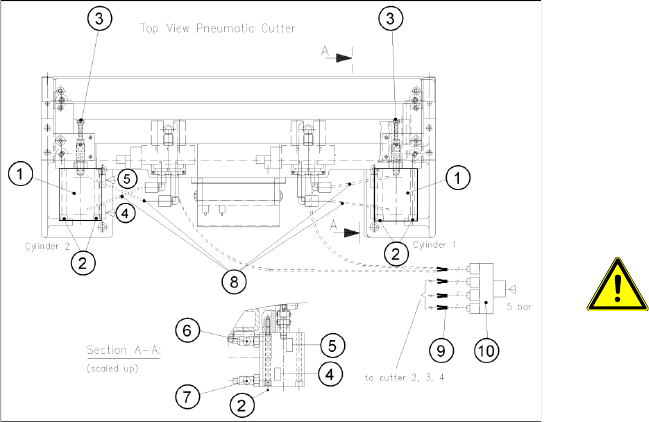
X Plug the compressed air connection to the
machine into the Y socket union (9) (in the
cable duct).
X Place the cover back on the control board and
the cable duct.
X Fit the empty-tape duct assembly and check
the gap between the empty-tape baffle, inside
and the leading edge of the tape deflector.
X In this position tighten all 4 screws crosswise.
CAUTION:
X Tighten the screws to the correct
torque.
X Perform the appropriate “Final Steps”.

Service Work
Component Handling Cutter
92 Service Manual SIPLACE D4
4.3.2.6 Turning the Stationary and Moveable Blade by 180 °
Removing the Blades
NOTE:
The movable blade has a cutting edge on both sides.
If one cutting edge becomes worn, the blade can still be used by turning it 180° on its vertical
axis and reinstalling it.
At the same time, the stationary blade must also be turned 180° on its vertical axis and installed.
If both edges are already blunt, replace the blades.
WARNING: Risk of injury!
There is a high risk of injury from the
blades and the tape deflector.
X Wear appropriately thick protective
gloves!
X Never reach into the cutter from
below or into the empty-tape duct
from above.
X Make sure that no-one can injure
themselves on the cutter, after it has
been dismantled and placed next to
the machine!
X Remove the cutter.(See section (4.3.2.5 Ex-
changing the Pneumatic Cutter
J
87 ) .)
X Dismantle the deflector plate (12): 4 hexagon
socket-head screws M4 x 8 (13).
Service Work
Cutter Component Handling
Service Manual SIPLACE D4
93
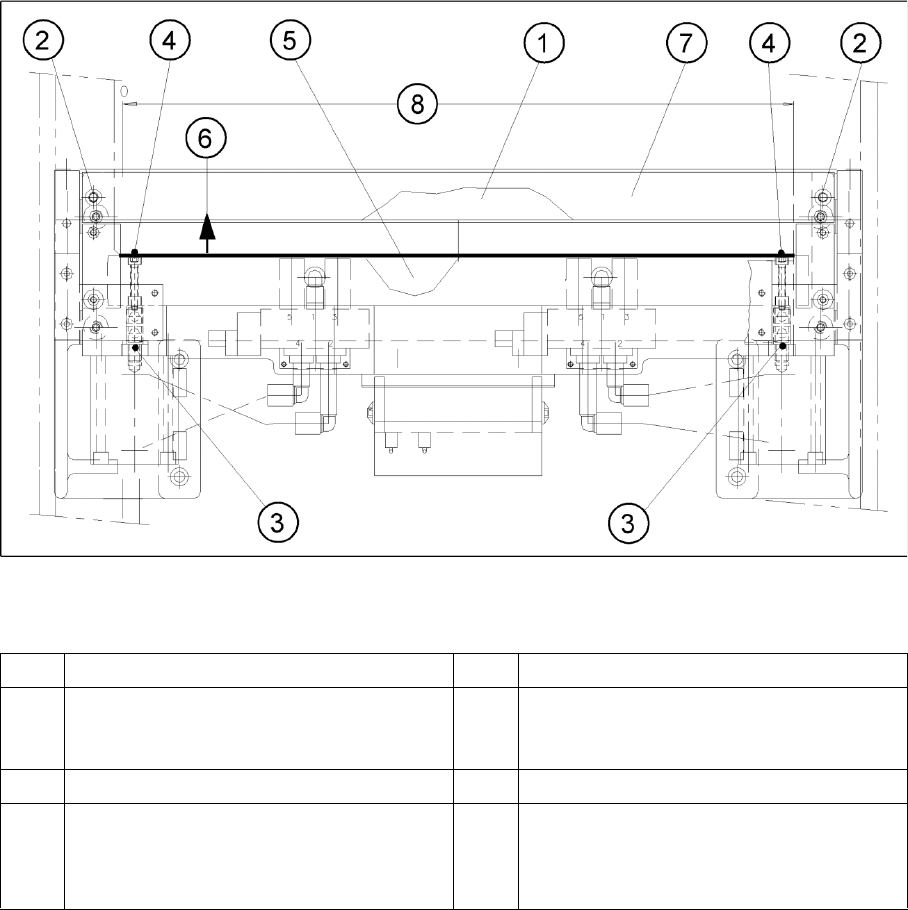
4-30: Removing/fitting the stationary and movable blade
Legend
X Loosen the screws fastening the stationary blade on the left and right (2).
X Mark the mounting position of the stationary blade (on the blade) with a water-insoluble marker (=
right end = right).
X Before any further disassembly, fasten the dismantled cutter to the retaining bracket (LH and RH)
with 2 parallel clamps, on a flat sturdy work bench, or screw it tight to the mounting plate with four
M6 hexagon socket head screws
X Remove the screw caps.
X Take hold of the stationary blade (1) by its ends and lift it up and out of the machine.
X Holding the articulated joint with a size 11 open-end wrench (3), loosen the screws fastening the
articulated joint in the movable blade (1 hexagon socket-head screw each on the right and left(4)).
X Push the movable blade in parallel (in the direction of the conveyor), until it is in the mounting position
of the stationary blade (for the direction of movement see (6)). Using a tool such as a screwdriver,
move the blade by alternately prying on the left and right next to the compressed air cylinder.
X Mark the mounting position of the movable blade (on the blade) with a water-insoluble marker (right
end = right).
X Lift the movable blade out of the cutter in this position.
1 Stationary blade 5 Movable blade (under the tape deflector)
2 Fixture for the stationary blade (under the
deflector plate): 2 hexagon socket head screws
M6 x 35
6 Direction for removing the movable blade
3 Articulated joint 7 Deflector plate
4 Screws fastening the articulated joint in the
movable blade:
1 hexagon socket head screw M4 x 25 DIN 912
each; strength 12.9, Loctite No. 243
8 Cutter area