00195166-0402_SM_D4_EN.pdf - 第228页
Settings C&P12 Adjusting the Stop for the Z Axis 228 Serv ice Manual SIPLACE D4 6.3.7.2 General From so ftware ver sion 60 1.01 onwar ds, dur ing th e r efe rence r un, the Z axis m oves into the star position with +…
Settings
Setting the Z axis Belt Tension C&P12
Service Manual SIPLACE D4
227
6.3.6 Setting the Z axis Belt Tension
6.3.7 Adjusting the Stop for the Z Axis
6.3.7.1 Tools and Equipment
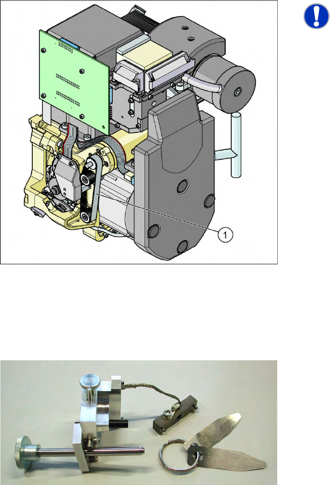
6-12: Measurement point for belt tension
NOTE:
The measurement point on the
measurement head should be in the
middle, between two deflection pulleys.
The measurement head should be kept
at a distance of maximum 2 - 3 mm
from the toothed belt.
Legend
1. Measurement point for the belt tension
X Hold the measuring head of the belt tension
measuring device in front of the toothed belt
(1) .
X Strike the toothed belt, to stimulate a vibration
of the toothed belt.
X If the belt tension frequency does not match
the value 280 Hz ±10 Hz, tension or relax the
belt via the drive motor fastening.
X Repeat these instructions until the belt tension
is correct.
6-13: Gauge for Z end stopper
Set of DIN 911 Allen keys
Gauge for Z axis end stopper - star gauge
[03019865-xx]
Settings
C&P12 Adjusting the Stop for the Z Axis
228 Service Manual SIPLACE D4
6.3.7.2 General
From software version 601.01 onwards, during the reference run, the Z axis moves into the star position
with +/-6250/6750 digits downwards or up into the crank, to determine the Z axis zero point correction
factor. The prerequisite for this is the correct setting of the upper end position stop of the Z axis. This
ensures that the Z axis is in the center of the raceway and that the Z axis zero point can be correctly
determined.
Preconditions:
Before you begin adjustment work, check the belt tension and the correct installation of the belt lock at
the Z axis.
6.3.7.3 Settings
X Switch off the machine. This setting can be performed directly at the machine.
X The star gauge for setting the Z end stopper is mounted on the C&P head in exactly the same way
as the zero point gauge for the star.
X Remove segment 1 and rotate the star until the gauge pin fits into the segment guidance.
X For better access to the Z axis end stopper, unscrew the cable clamp at one side and turn it to the
side. Then carefully push the flat ribbon cable to the side.
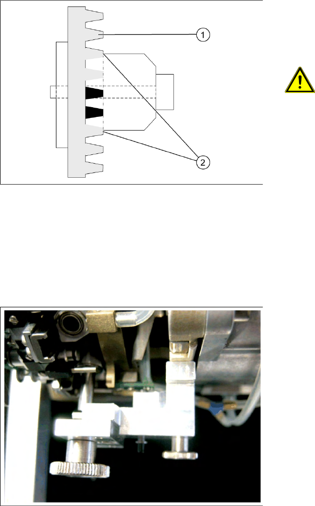
6-14: Clamping device Z axis
Legend
1. Belt tension Z axis
2. Tension jack is positioned on the teeth at the
top and bottom
ATTENTION:
Make sure that both ends of the tension
jack lie on the teeth of the toothed belt.
6-15: Z end stopper star gauge mounted
The star gauge ensures that the star is in the
correct position and that the Z axis is pressed
upwards.
Settings
Setting the Light Barrier Down C&P12
Service Manual SIPLACE D4
229
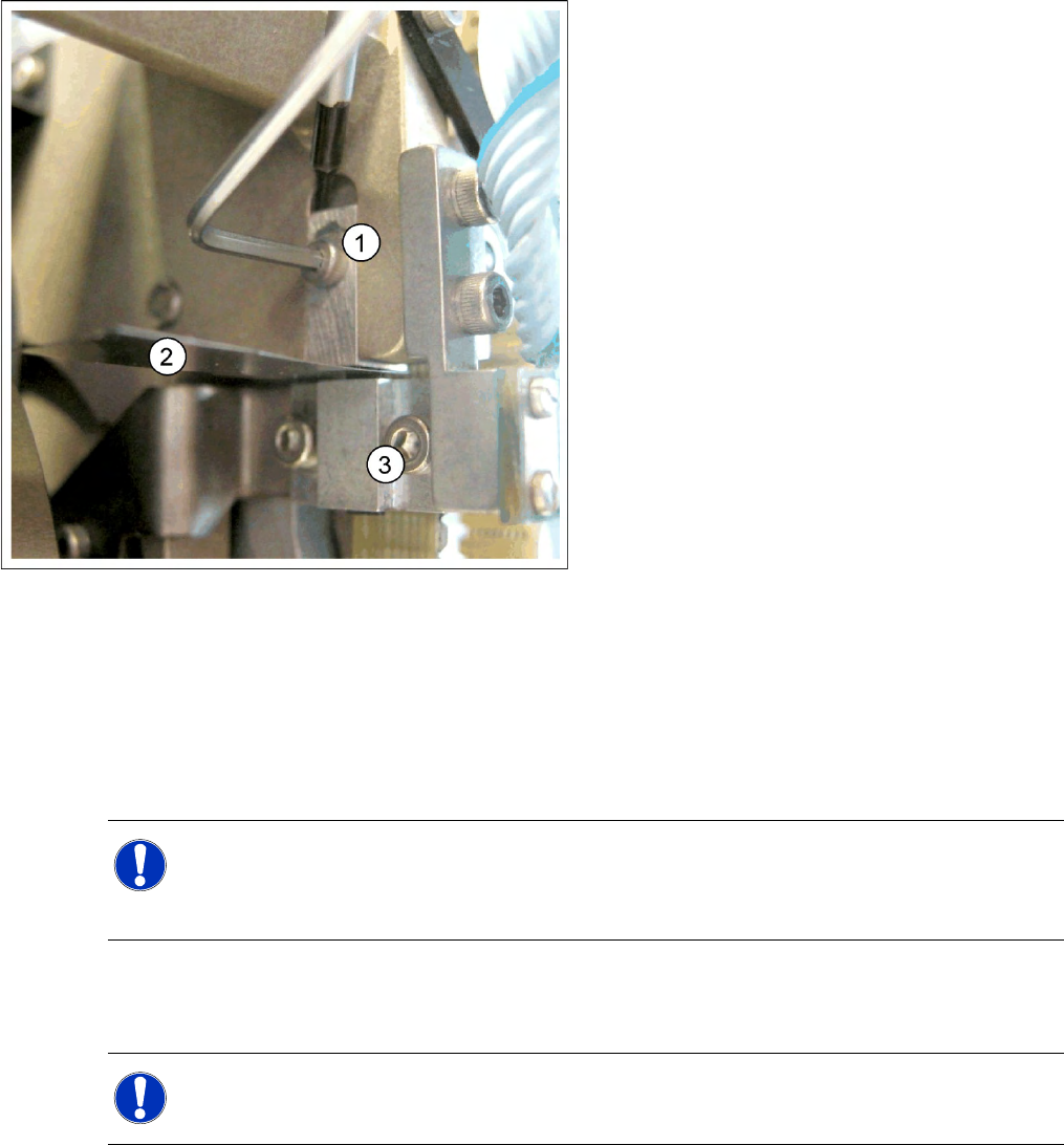
X Check whether the 5/100 mm feeler gauge passes easily (without resistance) between the Z axis
end stopper and the tension jack (see diagram above).
X If this is not the case, you will need to adjust the Z axis end stopper setting!
X Loosen the Z axis end stopper screw.
X Clamp a 15/100 mm feeler gauge between the Z end stopper and the clamp. Gently press the Z axis
end stopper downwards with the screwdriver and screw tight.
X It should now be more difficult to extract the 15/100 mm feeler gauge.
X Check again whether the 5/100 mm feeler gauge passes easily (without resistance) between the Z
axis end position stop and the tension jack. If this is not the case, you will need to readjust the setting!
6.3.8 Setting the Light Barrier Down
6-16: Z end stopper check and adjust
Legend
1. Z end stopper
2. Feeler gauge
3. Clamping device
NOTE:
When removing the gauge, make sure that the gauge pin is extracted first and that then the star
gauge is removed. If you do not observe this order, the gauge could catch in the segments and
damage these!
NOTE:
The light barrier is set with a test probe to a distance of 1.0 mm to the sleeve.