00195166-0402_SM_D4_EN.pdf - 第67页
Service W ork Replacing the Deflection Unit [00330938-02] Gantry Service Manual SIPLACE D4 67 4.2.6 Replacing the Defl ection Unit [00330938-02] 4.2.6.1 T ools and Equipment Set of DIN 911 Allen keys Belt tension mea…
Service Work
Gantry Replacing the Tensioning Keys [00329478-01, 00329485-01]
66 Service Manual SIPLACE D4
4.2.5.4 Installing the tensioning keys
4.2.5.5 Settings
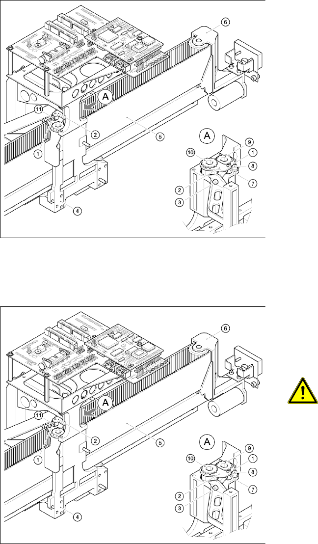
4-13: Replacing the tensioning keys
Installing the tensioning key, item 1
(synchronizing disk, short)
X Place the tensioning key on the "short
synchronizing disk" (9).
X Fasten the tensioning key with the M4 x 5
hexagon socket-head screw (8).
Installing the tensioning key, item 2
(synchronizing disk, long)
X Use the Benzing U clip to fit the spacer bolt (7)
onto the new tensioning key.
X Place the tensioning key on the "long
synchronizing disk" (10).
X Use the size 8 Allen key to turn the
synchronizing disk slightly until the hexagon
socket-head screw (3) can be screwed in.
X Pretension the toothed belt by turning the
hexagon socket-head screw clockwise.
4-14: Replacing the tensioning keys
X Push the head mount towards the X-axis
motor as far as the stop on the elastomeric
spring.
X Turn the hexagon socket-head screw to set
the belt tension to 53 Hz + 1/3 Hz.
CAUTION:
Do not overstretch the toothed belt
when adjusting the belt tension.
X Secure the hexagon socket-head screw (3)
with the locknut (11).
Service Work
Replacing the Deflection Unit [00330938-02] Gantry
Service Manual SIPLACE D4
67
4.2.6 Replacing the Deflection Unit [00330938-02]
4.2.6.1 Tools and Equipment
Set of DIN 911 Allen keys
Belt tension measuring device TSM [00326015-01]
"Measuring belt tensions" operating instructions
4.2.6.2 Parts
Deflection unit X [00330938-02]
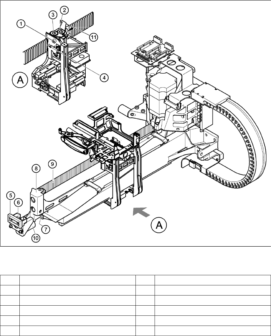
4.2.6.3 Removing the deflection unit
X Switch the machine off and secure it to prevent unauthorized reactivation, as described in section
4.3 from page 104 onwards.
X To relax the toothed belt (9), proceed as follows:
Loosen the locknut (11),
Turn the hexagon socket-head screw (1) counterclockwise.
X Remove the M4 x 35 hexagon socket-head screw (1).
X Pull the tensioning key (2) off the synchronizing disk (3).
X Pull the toothed belt (9) out through the opening in the tension jack (4).
X Unthread the toothed belt from the deflection unit (8).
X Loosen the two M3 x 8 hexagon socket-head screws (6) and remove the Y-brake "outside" (5).
X Loosen the two M6 x 10 hexagon socket-head screws (7) and remove the deflection unit ’X’ (8).
X Remove the elastomeric spring (10) from the deflection unit.
Service Work
Gantry Replacing the Deflection Unit [00330938-02]
68 Service Manual SIPLACE D4
4-15: Replacing the deflection unit
Legend
1 M4 x 35 hexagon socket-head screw 7 2 x M6 x 10 hexagon socket-head screws
2 Tensioning keys 8 Deflection unit - X
3 Synchronizing disk, long 9 Synchroflex toothed belt
4 Opening in tension jack for toothed belt 10 25 x 10.5 x 50 elastomeric spring
5 Y-axis brake, external 11 Locknut
6 2 x M3 x 8 hexagon socket-head screws