00195166-0402_SM_D4_EN.pdf - 第231页
Settings Setting the Mechanical Position of the Valve Positioning Drives C&P12 Service Manual SIPLACE D4 231 6.3.10 Setting the Mechanical Posi tion of the V alve Positioning Drives Set the motor po sition of the v…
Settings
C&P12 Determining the Zero Point Correction for the Star Axis of the C&P Head
230 Service Manual SIPLACE D4
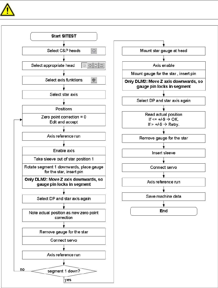
6.3.9 Determining the Zero Point Correction for the Star Axis of the C&P Head
6-17: Flow chart zero point correction
ATTENTION:
X When performing this task, follow all instructions exactly!
Settings
Setting the Mechanical Position of the Valve Positioning Drives C&P12
Service Manual SIPLACE D4
231
6.3.10 Setting the Mechanical Position of the Valve Positioning Drives
Set the motor position of the valve positioning drives "pickup/placement" and "reject" as shown in the
following diagram.
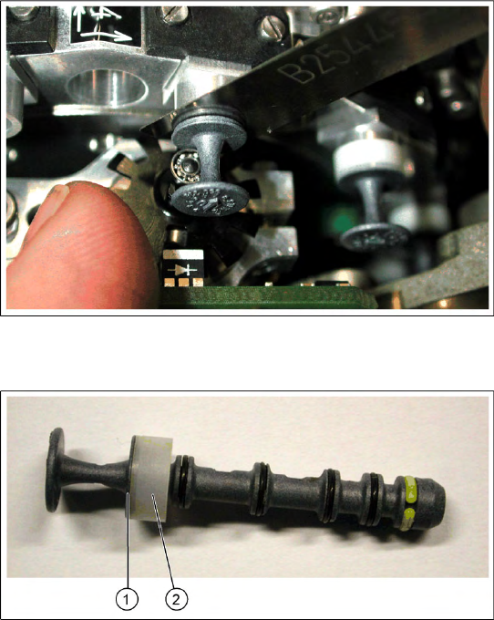
If the new valve plungers are used (s. diag. below) proceed as follows: Take out one valve plunger
and remove the sleeve (2).
Insert the plunger without bushing and carry out the following steps on this segment:
Insert the distance gauge (0.2 mm) between valve plunger and valve casing.
Rotate the valve positioning drive 90 degrees from its initial position. The eccentric of the valve
adjustment drive will just touch the inner side (1) of the valve plunger.
Fix the motor of the valve drive in this position.
Remember to replace the tube on the valve plunger.
6-18: Setting the mechanical position of the valve drive
Set the motor position of the valve positioning
drives "pickup/placement" and "reject" as shown in
the diagram.
6-19: New valve plunger [00351498-03]
X If the new valve plungers are used (s. diag. on
left) proceed as follows:
Take out one valve plunger and remove the
sleeve (2).
Insert the plunger without bushing and carry
out the following steps on this segment:
X Insert the distance gauge (0.2 mm) between
valve plunger and valve casing.
X Rotate the valve positioning drive 90 degrees
from its initial position. The eccentric of the
valve adjustment drive will just touch the inner
side (1) of the valve plunger.
X Fix the motor of the valve drive in this position.
X Remember to replace the tube on the valve
plunger.
Settings
C&P12 Adjustment of air pressure values
232 Service Manual SIPLACE D4
6.3.11 Adjustment of air pressure values
6.3.11.1 Tools and Equipment
A set of slotted screw drivers
Compressed air testing device
6.3.11.2 Setting the Air Blast Pressure Values
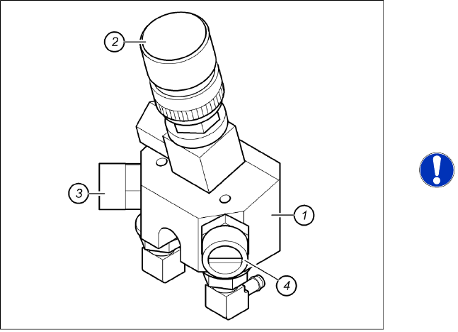
6-20: Adjustment of air pressure values
Legend
1. Forced air unit
2. Micro-relay valve
3. Adjustment valve for the reject circuit
4. Adjustment valve for the pickup / placement
circuit
NOTE:
Use a nozzle of type 914 to set the air
blast. Press in the spring from the
nozzle interface during the
measurement and read the value from
the display.