00195166-0402_SM_D4_EN.pdf - 第155页
Service W ork Replacing the Turning Station (D Se ries) [ 00341780-xx] C&P12 P lacement Head Service Manual SIPLACE D4 155 4.5.5 Replacing the T urning St ation (D Series) [00341780-xx] Removal/Installation Legend 1.…

Service Work
C&P12 Placement Head Replacing the Intermediate Distributor [00330648]
154 Service Manual SIPLACE D4
Connectors Description
X1, 40-pole Connected to plug X14 on the head board
Voltage supply, tacho and track signals for the Z axis drive
Signal from light barrier "Z axis in top position"
Signal from light barrier "Z axis in bottom position" (sensor stop signal)
Control signal for the air blast valve
Supply voltage +5 VDC, ±15 VDC
Reference point signal for the DP axis
Track signals for the DP axis
X2, 40-pole Connected to plug X13 of the gantry head distributor
Voltage supply and track signals for the star axis drive
Reference point for the star axis
Analog air blast pressure value
Supply voltages +5 VDC, ±15 VDC, +24 VDC
X3, 10-pole Connection for the Z motor and Z tacho signal (Tacho signal is not used on the HF machine)
X4, 10-pole Connection for the Z axis track signals
X5, 10-pole Connection for the star motor
X6, 6-pole Connection for the air blast valve
X7, 10-pole Connection for the DP axis track signals
X10, 10-pole Connection for the "Z axis up" signal
X11, 8-pole Connection for the light barrier "Z axis down" signal (sensor stop signal)
X12, 10-pole Connection for the star axis track signals
X13, 10-pole Test connection for the Z axis track signals
X14, 10-pole not used
X15, 10-pole Test connection for the star axis track signals
X16, 10-pole Test connection for the DP axis track signals
Service Work
Replacing the Turning Station (D Series) [00341780-xx] C&P12 Placement Head
Service Manual SIPLACE D4
155
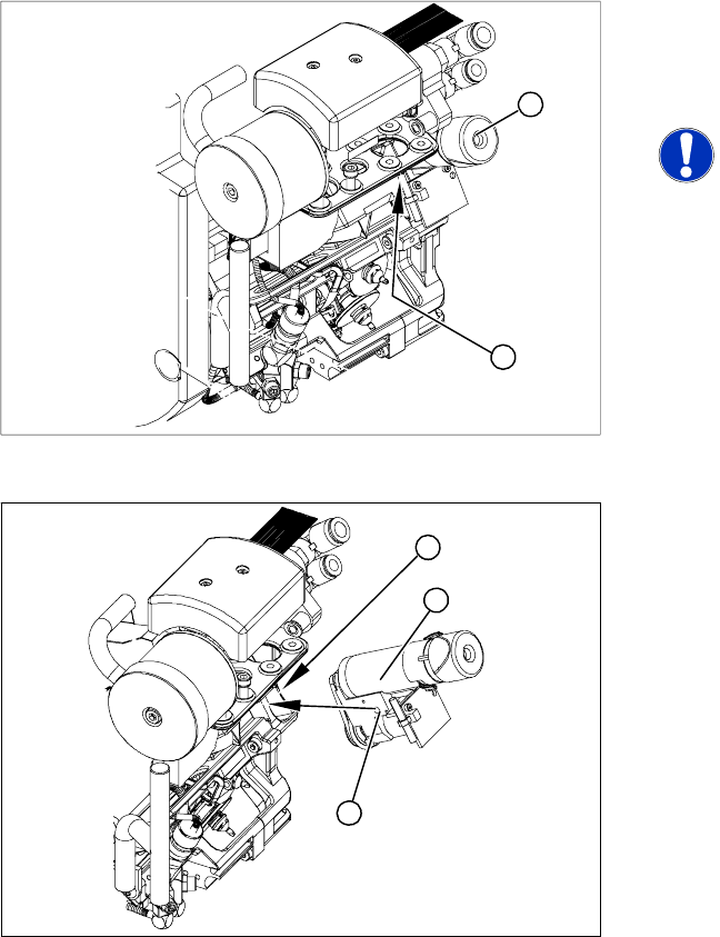
4.5.5 Replacing the Turning Station (D Series) [00341780-xx]
Removal/Installation
Legend
1. Turning station
2. Fastening screw for turning station
NOTE:
The head does not need to be removed
when dismantling the turning station.
X Switch off the machine and secure it to prevent
unauthorized reactivation.
X Open the strain relief at the gantry head
distributor.
X Disconnect the motor cable and flat ribbon
cable from the sockets on the gantry head
distributor.
1
2
X Loosen the screw fastening the turning station
(2).
X Carefully lever the turning station (1)
backwards, off the locating pins and gently pull
it (1) out.
X Make sure that the contact surfaces on the
turning station and back part (3) are clean.
X Insert the turning station holes (1) onto the
parallel pins.
X Carefully push the turning station towards the
front part until it reaches the stop.
X Move the C&P head to a suitable position.
(Move the X/Y gantry axes so that you can
easily access the turning station.)
X Fasten the turning station with the screw
provided (2).
X Plug the cable into the slots on the gantry head
distributor. Make sure the cables are run
correctly.
X Fasten the strain relief at the gantry head
distributor.
X Switch the machine on and start it up.
X Use the SITEST program to run a function test.
3
1
2
Service Work
C&P12 Placement Head Replacing the DP Rocker
156 Service Manual SIPLACE D4
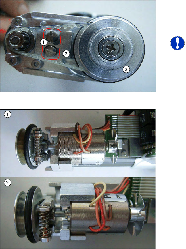
4.5.6 Replacing the DP Rocker
The swivel-in rocker of the DP station has been fitted with 2 cones from version 7 onwards. The DP
station [00320041-05] can be upgraded to accommodate this improvement by simply replacing the old
part.
Tools and Equipment
Standard tool
Retrofit assembly for rocker [03063649S01]
Belt tensioning device for DP station
Removal
X Carefully disconnect the toothed belt from the
motor toothed wheel.
X Loosen the two screwed fittings on the rocker
arm.
NOTE:
The rocker arm is located under the
drive arm (3). The drive arm is fixed to
the rocker arm with the two screws (1).
X Swing the rocker arm on the motor to one side
and remove the rocker arm with drive wheel
(2) from the swivel-in ball bearing.
The adjacent diagram shows a comparison of the
spring mechanism on the DP rocker with version 5
(1) and version 7 (2) plus 2 cones.