00195166-0402_SM_D4_EN.pdf - 第179页
Service W ork Replacing the Forced Air Unit [00367793-xx] C&P12 P lacement Head Service Manual SIPLACE D4 179 4.5.15 Replacing the Forc ed Air Unit [00367793-xx] Removal Legend 1. Forced air unit / DLM2 2. To the &qu…
Service Work
C&P12 Placement Head Replacing the Complete Z Axis [03001959]
178 Service Manual SIPLACE D4
Installation
X (1) Rotate the star into the position shown and
then pull the Z axis out of the guide, by holding
on to its assembly plate.
Clean the contact surface with SIPLACE
cleaning tips and ethanol.
X (2) Push the new Z axis guide into the groove
provided.
Press the reference edge (inner side) of the Z
axis into the groove and fix the Z axis with the
screws provided.
X (3) Use the feeler gauge to check the gap
between the jaws and the side edges of the
circular arc guide.
The permissible gap is between 0.02 and 0.03
mm.
Readjust the jaw if necessary.
Reassemble the placement head as follows.
NOTE:
The board must be fitted centered to
the jaws.
X Make sure that the board does not
rub against the frame (check with
gauge if necessary).
Complete the following step at every second
service interval for the head:
X (4) Use the mini oiler device to apply a small
amount of oil [00367071-xx] to the drilling
provided.
Make sure that there is not too much oil oozing
out of the hole.
NOTE:
Where dirt is not excessive, the oil can
be directly applied to the rail.
Refit the front part of the C&P head. (See section
(4.5.2 Removal/Installation of Head Front Part
J
149 ) .)
Service Work
Replacing the Forced Air Unit [00367793-xx] C&P12 Placement Head
Service Manual SIPLACE D4
179
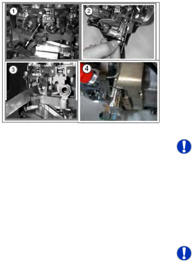
4.5.15 Replacing the Forced Air Unit [00367793-xx]
Removal
Legend
1. Forced air unit / DLM2
2. To the "placement circuit" compressed air tube
and the compressed air sensor on the
intermediate distributor
3. To the "reject circuit" compressed air tube
4. 2 M3x20 hexagon socket-head screws
5. SW8 union nut for the compressed air
connection
X Move the changeover table out of the
machine.
X Switch off the machine.
X Remove the cable plug from the slot on the
intermediate distributor.
X Detach the black compressed air hose from
the plug-in coupling on the vacuum distributor.
X Dismantle the intermediate distributor.
X Detach the compressed air sensor.
X Detach the compressed air hose for the
placement position (2) from the "placement
circuit" compressed air tube.
X Detach the compressed air hose for the reject
position (3) from the "reject circuit"
compressed air tube.
X Loosen the two hexagon socket-head screws
(4).
X Remove the forced air unit (1).
X Loosen the union nut (5) and detach the
compressed air supply hose.
Service Work
C&P12 Placement Head Replacing the Silencer [03003134]
180 Service Manual SIPLACE D4
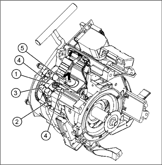
Installation
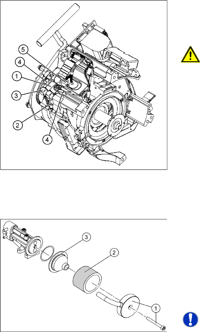
4.5.16 Replacing the Silencer [03003134]
Removal/Installation
X Reconnect the hoses.
X Fix the forced air unit (1) with the two hexagon
socket-head screws (4).
X Connect the plug to the slot on the
intermediate distributor.
ATTENTION: Risk of injury!
Risk of injury from the compensating
tube when the hose is pushed onto the
measuring tube!
X Fit the intermediate distributor.
4-49: Silencer
Legend
1. Fastening screw and cover flap with
discharged air tube
2. Silencer
3. Pre-silencer
X Loosen and remove the fastening screw (1).
Detach the discharged air hose.
X Remove the silencer (2).
X Remove the pre-silencer (3) from the silencer.
NOTE:
X Always wear gloves when handling
new silencers.
X Insert the pre-silencer and the screw provided
and fasten the silencer. Reconnect the
discharged air hose.