00195166-0402_SM_D4_EN.pdf - 第75页
Service W ork Replacing the X Motor Unit [00333167-03] Gantry Service Manual SIPLACE D4 75 Gantry 1 or 3 X Remove the black cover strip on the cross-beam abo ve the gantry concerned: Unplug the fan ca ble. The fan is f…
Service Work
Gantry Replacing the X Motor Unit [00333167-03]
74 Service Manual SIPLACE D4
4.2.8 Replacing the X Motor Unit [00333167-03]
Tools and Equipment
Set of DIN 911 Allen keys
Cable ties
Belt tension measuring device TSM [00326015-01]
"Measuring belt tensions" operating instructions
Parts
X motor unit [00333167-03]
Removing the X-axis motor unit
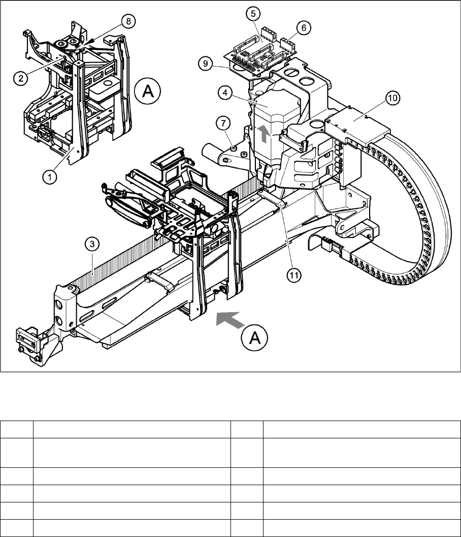
4-22: Replacing the X-axis motor unit
Legend
X Switch off the machine and secure it to prevent unauthorized reactivation.
1 Head mount 7 2 x M6x14 hexagon socket-head screws
2 M4 x35 hexagon socket-head screw for
tensioning the X toothed belt
8Locknut
3 Synchroflex X-axis toothed belt 9 Board holder
4 X-axis motor unit 10 Cable clamps
5 X/Y distributor 11 Cable clamp
6 X5 socket for X-axis motor

Service Work
Replacing the X Motor Unit [00333167-03] Gantry
Service Manual SIPLACE D4
75
Gantry 1 or 3
X Remove the black cover strip on the cross-beam above the gantry concerned:
Unplug the fan cable. The fan is fixed to the black cover strip.
Remove the black cover strip (3 M6x8 hexagon socket-head screws).
X Cut the cable ties holding the X-axis motor cable.
X Remove the cable clamp for the flat ribbon cable (11).
X Disconnect all the plugs from the X/Y distributor (5).
X Remove the X/Y distributor (5).
X Remove the board holder for the X/Y distributor (9).
X Remove the cable holders (10) on the trailing cable.
X To relax the toothed belt (3), proceed as follows:
Loosen the locknut (8),
Turn the hexagon socket-head screw (2) counterclockwise.
X Loosen the two M6 x14 hexagon socket-head screws (7) fixing the X motor unit (4).
X Pull the X motor unit (4) up and out,
X at the same time pushing the board holder slightly to the side.
Gantry 2 or 4
X Remove the black cover strip on the cross-beam above the gantry concerned:
Unplug the fan cable. The fan is fixed to the black cover strip.
Remove the black cover strip (3 M6x8 hexagon socket-head screws).
X Cut the cable ties holding the X-axis motor cable.
X Remove the cable clamp for the flat ribbon cable (11).
X Disconnect all the X motor plugs from the X/Y distributor (5).
X Remove the board holder for the X/Y distributor (9).
X Remove the cable holders (10) on the trailing cable.
X To relax the toothed belt (9), proceed as follows:
Loosen the locknut (8),
Turn the hexagon socket-head screw (2) counterclockwise.
X Loosen the two M6 x14 hexagon socket-head screws (7) fixing the X motor unit (4).
X Pull the X motor unit (4)
up and out,
at the same time pushing the board holder slightly to the side.
DANGER: POWERFUL MAGNETIC FIELD
X Always follow the special safety instructions when working in the vicinity of powerful magnetic
fields.
Service Work
Gantry Replacing the X Motor Unit [00333167-03]
76 Service Manual SIPLACE D4
Installing the X-axis motor unit
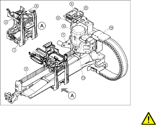
4-23: Replacing the X-axis motor unit
Gantry 1 or 3
X Carefully insert the X motor unit (4) as far as
the stop,
making sure that you do not damage the
toothed belt. The motor cable points towards
the permanent magnets of the linear drive.
X Fix the X motor unit into place with the two
hexagon socket-head screws (7).
X Fit the cable holders for the trailing cable (10).
X Fit the board holder (9).
X Fit the X/Y distributor (5).
X Connect all plugs to their sockets on the X/Y
distributor (5).
X Fix the flat ribbon cable with the cable clamp
(11).
X Fix all the cables with cable ties.
CAUTION:
Make sure that the cables are firmly
seated. Otherwise, the high
acceleration forces may cause the
cable to slip out of position and shear
through.
X Tension the X toothed belt with the hexagon
socket-head screw (2).
X Use the three M6 x 8 hexagon socket-head
screws to fit the black cover strip to the
crossbeam above the gantry concerned.
X Connect the cable of the fan motor to the
socket.