00195166-0402_SM_D4_EN.pdf - 第9页
Introduction Serial Number of D4 Module Safety Instructions Service Manual SIPLACE D4 9 1I n t r o d u c t i o n This service guide is a manual or reference wor k for performing service work on the SIPLACE® D4 placement …
Table of contents
8 Service Manual SIPLACE D4
6.4.2 Tape Cutter Control Unit ..................................................................................................................... 240
6.4.3 Check the gap between the empty-tape baffle, inside and the leading edge of the tape deflector..... 241
6.5 Conveyor............................................................................................................................................242
6.5.1 Adjusting the Tension of the Conveyor Toothed Belt.......................................................................... 242
6.5.1.1 Measuring Points and Belt Tensions for D4 Conveyor ..................................................................... 244
6.5.2 Setting the fixed conveyor side (single and dual conveyor) ................................................................ 245
6.5.2.1 General Notes ................................................................................................................................... 245
6.5.2.2 Widening the Conveyor (Flexible Dual Conveyor for Single Conveyor Mode).................................. 246
6.5.2.3 Connecting the Dual Conveyor Lifting Tables................................................................................... 247
6.5.2.4 Converting the Single Conveyor Mode Back to Flexible Dual Conveyor Mode ................................ 247
6.5.3 Moving the Fixed Conveyor Edge for ’Extra Wide Conveyor’ ............................................................. 248
6.5.4 Checking the Limit Switch Position ..................................................................................................... 249
6.5.4.1 Adjusting the Limit Switch for Initializing the Adjustment Unit........................................................... 250
6.5.5 Width Adjustment Unit......................................................................................................................... 250
6.5.5.1 Setting the Proximity Switch on the Adjustment Unit ........................................................................ 250
6.5.5.2 Setting the Pneumatic Cylinder Proximity Switch on the Adjustment Unit ........................................ 251
6.5.6 Setting the Laser Light Barrier for the Stopper Position...................................................................... 251
6.5.7 Function "Constant Transport Time in Placement Area"..................................................................... 253
6.5.8 Light Barrier Functions in Input, Intermediate and Output Conveyors ................................................ 254
6.5.9 Setting the Clamping Actuator ............................................................................................................ 254
6.5.10 Board Clamping Functions.................................................................................................................. 255
6.5.10.1 Setting Board Clamping .................................................................................................................... 256
6.5.11 Lifting Table Functions ........................................................................................................................ 257
6.5.11.1 Adjusting the Speed of the Lifting Table (from SW 602) ................................................................... 257
6.5.11.2 Setting the Lifting Table Unit [00358684-05]..................................................................................... 259
6.5.12 Conveyor Control TSP 301 ................................................................................................................. 259
6.5.12.1 Jumper Settings for TSP 301 ............................................................................................................ 259
6.5.12.2 Conveyor Control TSP 301 with Siemens Interface.......................................................................... 261
6.5.12.3 LED Display on Conveyor Control TSP 301 ..................................................................................... 262
6.5.12.4 Assignment Table: LEDs on the TSP 301 Conveyor Control............................................................ 262
6.5.12.5 Siemens/SMEMA TSP 301 Interface Description .............................................................................266
Introduction
Serial Number of D4 Module Safety Instructions
Service Manual SIPLACE D4
9
1Introduction
This service guide is a manual or reference work for performing service work on the SIPLACE® D4
placement machines.
1.1 Safety Instructions
1.1.1 Serial Number of D4 Module
1.1.2 Environmentally-Friendly Disposal of Materials and Components
SIPLACE products are manufactured using only materials and parts that can be easily separated and
disposed of in an environmentally-friendly way. Hazardous materials are not necessary for the
installation, dismantling or operation of the machine.
1.1.3 Use of Original SIPLACE Accessories and Spare Parts
Only use S,3/$&( original spare parts and authorized accessories. The use of other parts will affect
safety and will invalidate the liability for any consequential damage.
DANGER: Nonobservance of these safety instructions may cause injury to personnel and
damage to the machine!
X Please observe the safety instructions in the operating manual of the according machine for
all service work!
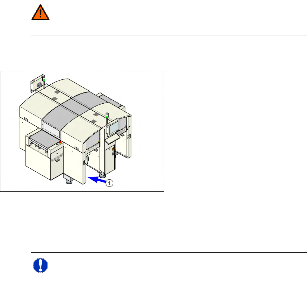
The serial number of your placement machine can
be found on the typeplate (1).
NOTE:
The company operating the system has sole responsibility for the proper, environmentally-
friendly disposal of machines, working materials, consumables and wear parts.
X Please observe your national statutory provisions for waste disposal and environmental
protection.

Introduction
Key Information Information About This Service Manual (Customer Version)
10 Service Manual SIPLACE D4
1.2 Key Information
1.2.1 Information About This Service Manual (Customer Version)
The service work described in this manual may only be performed by specially trained service
technicians, with appropriate qualifications and expertise.
If you should have any questions during the service work, please contact the SIPLACE customer hotline
directly:
(0049) 089 20800 48642
or send an e-mail to: hotline.siplace@siSODFH.com.
1.2.2 Validity of Document
This document contains instructions about the service work for all D3 machines from the SIPLACE D
series.
The service work is listed on a module by module basis:
If the work required for specific machines should differ from the standard procedure, this will be
indicated with reference to the machine number, series and various delivery statuses.
Diagrams should be seen as examples e.g. the diagram of a machine with different paint finish does
not mean that the following information only applies to the machine type shown.
The main focus of this manual is on a description of mechanical service work.
Please refer to the circuit diagram folder supplied with your machine for any electrical checks:
Siplace D3 circuit diagram folder, item no. 00195091-xx (German and English)
1.2.3 Release History
1.2.4 Further Information
If you have any questions about this manual or if you would like more information about certain subjects,
please contact your local 6,3/$&( branch or us directly:
$60 A
ssembly Systems*PE+&R.*
Rupert-Ma
yer-Str. 44
81379 Munich
Release Changes
07/2007
(initial release)
(after data migration)
08/2008 Corrected version
For example Revision of the C&P and Twin Head chapters