00195166-0402_SM_D4_EN.pdf - 第255页
Settings Board Clamping Functions Conveyor Service Manual SIPLACE D4 255 6.5.10 Board Clamping Functions Function description: The PCB moves into the place ment area, it is recogn ized by the light barrier, stops at th…
Settings
Conveyor Light Barrier Functions in Input, Intermediate and Output Conveyors
254 Service Manual SIPLACE D4
6.5.8 Light Barrier Functions in Input, Intermediate and Output Conveyors
Recognizing and stopping the PCB boards.
Monitoring the boards in the input conveyor i.e.
If a board is recognized in the input conveyor, it will appear on the operating interface and the
machine will lock the conveyor interface to the previous station. When using boards with outbreaks,
the board may stop although the signal of the light barrier is disabled and the interface to the previous
station is opened again. Then the next PCB would move into the input conveyer with the PCB still
lying in the input conveyer. The board monitoring function moves the board backwards and then
transports it forwards again, until the light barrier switches.
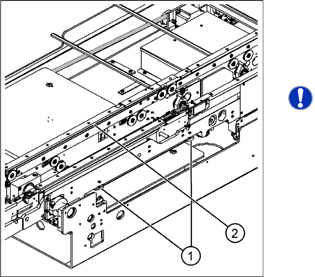
6.5.9 Setting the Clamping Actuator
Legend
1. Actuator
2. Top edge of conveyor belt
X Set the distance between the actuator and the
top edge of the conveyor belt to 94 mm.
NOTE:
The distance between the clamping
actuator (lifting table) and the top edge
of the belt must be checked at all four
contact points.
Settings
Board Clamping Functions Conveyor
Service Manual SIPLACE D4
255
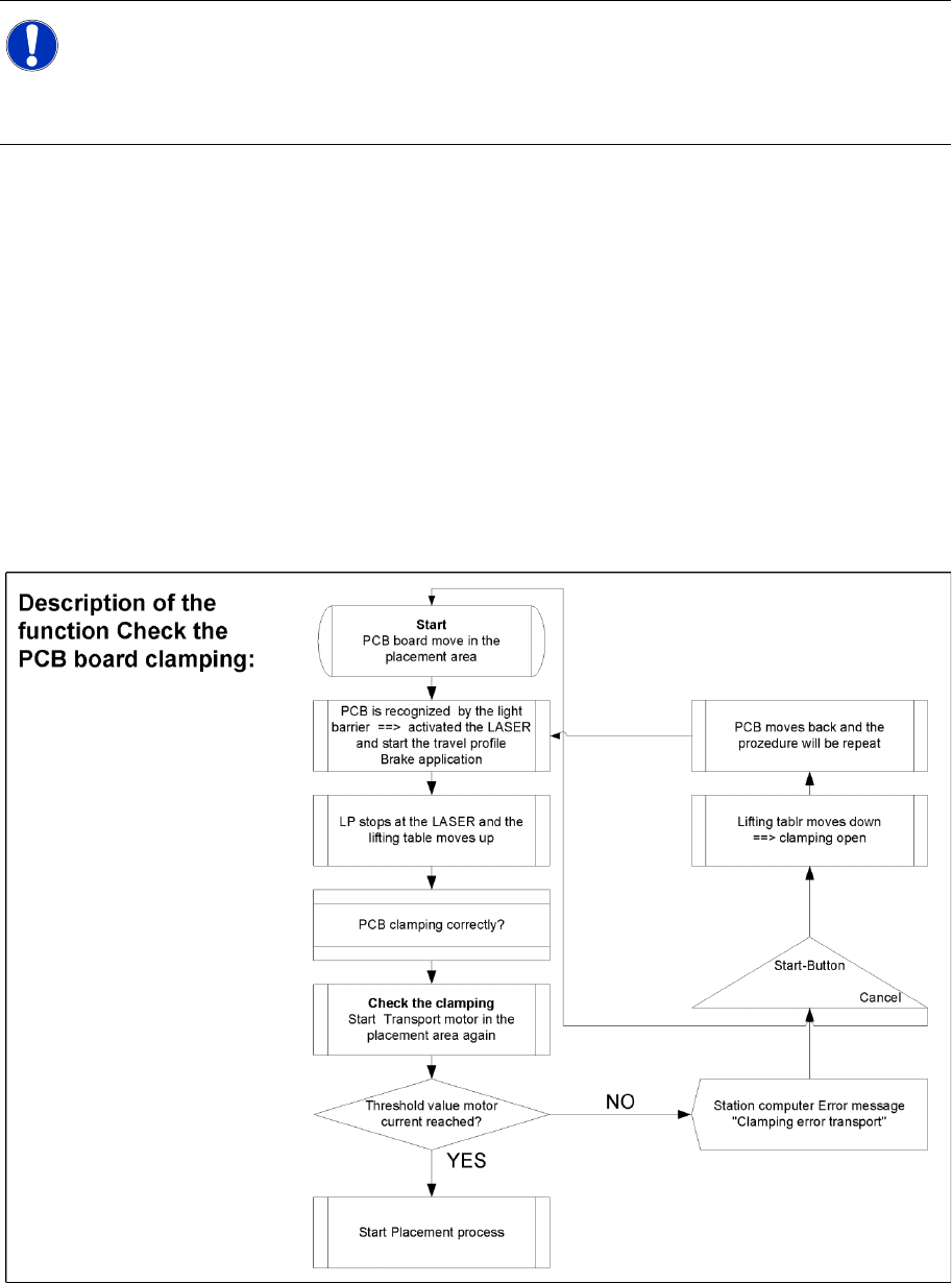
6.5.10 Board Clamping Functions
Function description:
The PCB moves into the placement area, it is recognized by the light barrier, stops at the laser and
the lifting table moves up.
Check PCB clamping: The conveyor motor in the placement area will start again. If the PCB is
clamped correctly the motor current will rise up and reach a defined threshold value. Once the board
has been correctly clamped into place, the placement process will begin.
If this threshold is not reached, the system assumes that the board is on its way to the intermediate
or output conveyor and has therefore not been correctly clamped into place.
The station computer will issue the message "PCB not correctly clamped PA1 (PA2)". The process
can be repeated by pressing the "start button".
The lifting table will move downwards, the board will be transported back and the stopper position
will be approached again.
NOTE:
The check whether a PCB is clamping correctly, is controlled by adding the conveyor motor
currents over a defined period.To check the function you can place a distance plate under the
conveyor side, so that the lifting table can not move to the upper position.
The check is not performed if the option "Vacuum Tooling" is installed.
Settings
Conveyor Board Clamping Functions
256 Service Manual SIPLACE D4
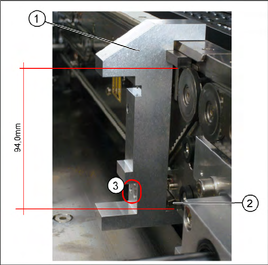
6.5.10.1 Setting Board Clamping
6-38: Setting the actuator
Legend
1. Gauge [00369202-01]
2. Actuator
3. Drilling, for fixing the actuator screws, when
the gauge is fitted
If the conveyor control issues the error
Clamping
error transport
, check the distance from the lifting
table actuator to the top edge of the conveyor belt.
Use the setting gauge to check and set the
actuator. The distance from the clamping actuator
(lifting table) to the top edge of the belt should be
94.0 mm at all four contact points. (see diagram)