00195166-0402_SM_D4_EN.pdf - 第151页
Service W ork Replacing the Component Camera (D Series) [03014449- xx] C&P12 Placement Head Service Manual SIPLACE D4 151 4.5.3 Replacing the Component Camera (D Series) [03014449-xx] Removal/Installation The compone…
Service Work
C&P12 Placement Head Removal/Installation of Head Front Part
150 Service Manual SIPLACE D4
Installation
See also:
J
6.3.1 Calibrating the C&P Head and Cameras [
J
221]
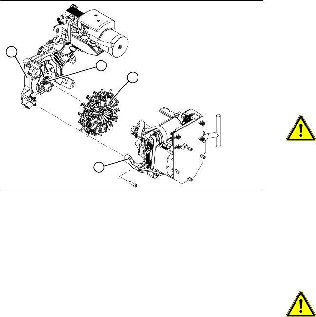
X Grease the O-rings of the vacuum distributor
with Unisilkon.
X Push the small O-ring onto the tube.
X Place the large O-ring on the vacuum
distributor piece (4).
X Check that the O-rings are seated correctly.
X Insert the distributor block into the back part
(3).
ATTENTION:
Star position 15°!
X Make sure that all contact surfaces and pins
are clean.
X Place the front part (2) on the back part (3) so
that the parallel pins are aligned with the holes
in the front part.
X Carefully push the front part against the back
part until it lies flat against the back part.
X Tighten the four fastening screws.
X Reconnect to the electrical and compressed
air systems.
ATTENTION: Check how the cables
are run!
Make sure that the folded part of the
ribbon cable for the "Z axis up" light
barrier is pushed back under the
illumination board.
X Use the SITEST program to calibrate the C&P
head.
1
4
3
2
Service Work
Replacing the Component Camera (D Series) [03014449-xx] C&P12 Placement Head
Service Manual SIPLACE D4
151
4.5.3 Replacing the Component Camera (D Series) [03014449-xx]
Removal/Installation
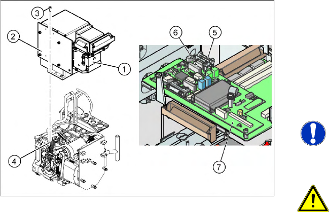
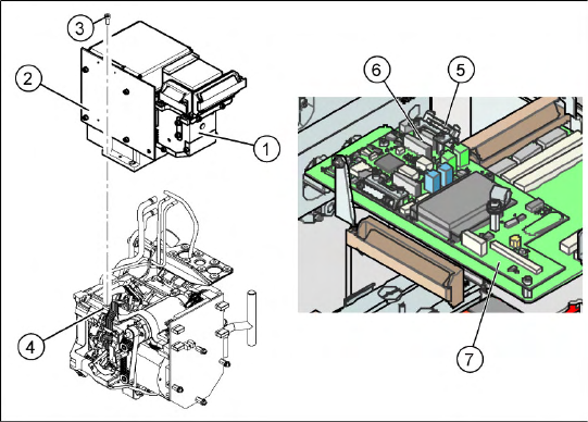
The component camera must be replaced as a
complete unit. This consists of the lens system,
camera, amplifier, illumination planes and
"illumination controller" board.
Article numbers
SST28 [03014449-xx]
SST29 [03018637-xx]
NOTE:
You may need to completely dismantle
the front part of the head (4), so that the
components can be more easily
accessed.
ATTENTION: Do not damage the
fixture clips!
To disconnect the component and PCB
camera connections, you need to open
the fixture clips by applying pressure to
the side of the connector.
X For details see section (4.5.22 Press
Fit Connections with Fixture Clips on
the Vision Board (D Series)
J
196 )
X Disconnect the flat ribbon cable holders (5) at
the Vision board (7) of the gantry head
distributor.
X Pull both flat ribbon cable connectors (6) off
the Vision board of the gantry head
distributor (2).
X Loosen the four screws (3) holding the
component camera.
X Carefully lift off the component camera (1).
Service Work
C&P12 Placement Head Replacing the Component Camera (D Series) [03014449-xx]
152 Service Manual SIPLACE D4
Installation
See also:
J
6.3.1 Calibrating the C&P Head and Cameras [
J
221]
X Make sure that all contact surfaces are clean.
X Place the holes in the camera on the parallel
pins (4).
X Carefully position the camera on the C&P
head, until the camera plinth lies flat on the
contact surface of the front part of the C&P
head.
X Fix the camera in place with the four screws
provided (3).
X Fit the front part of the C&P head (4).
X Reconnect the flat ribbon cables (6) to the
Vision board (7) of the gantry head distributor.
X Refit the flat ribbon cable strain relief (5). This
reestablishes the ground connection.
X Start the machine.
X Use the SITEST program to calibrate the C&P
head.