00195166-0402_SM_D4_EN.pdf - 第194页
Service Work C&P12 Placement Head Checking the Cab le Routing 194 Serv ice Manual SIPLACE D4 4.5.21.2 X Gantry Cable Routing 4.5.21.3 Component Sensor Cable Routing Avoid damage from the Y gantry. Make sure that the …
Service Work
Checking the Cable Routing C&P12 Placement Head
Service Manual SIPLACE D4
193
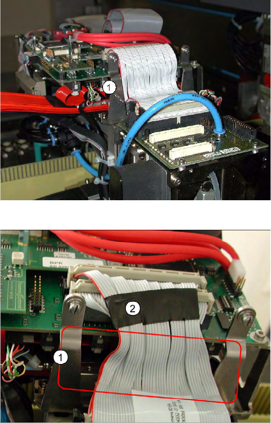
Avoid damage from old supporting plates
Old supporting plates have a gap which is too
narrow for the flat ribbon cable. This could lead
to the flat ribbon cable insulation being
damaged.
If the flat ribbon cable rubs against the
supporting plate, see item (1), either replace
the supporting plate or reduce the width of the
flat ribbon cable accordingly in the vicinity of
the gap (2).
Reducing the width of the flat ribbon cable
The width of the flat ribbon cable can be
reduced around the gap (1) by using a wide
heat-shrinkable sleeve or insulating tape (2).
If the flat ribbon cable is damaged, replace it.
Use the "Cable /S-D placement head"
[03047845-xx] for this.
Service Work
C&P12 Placement Head Checking the Cable Routing
194 Service Manual SIPLACE D4
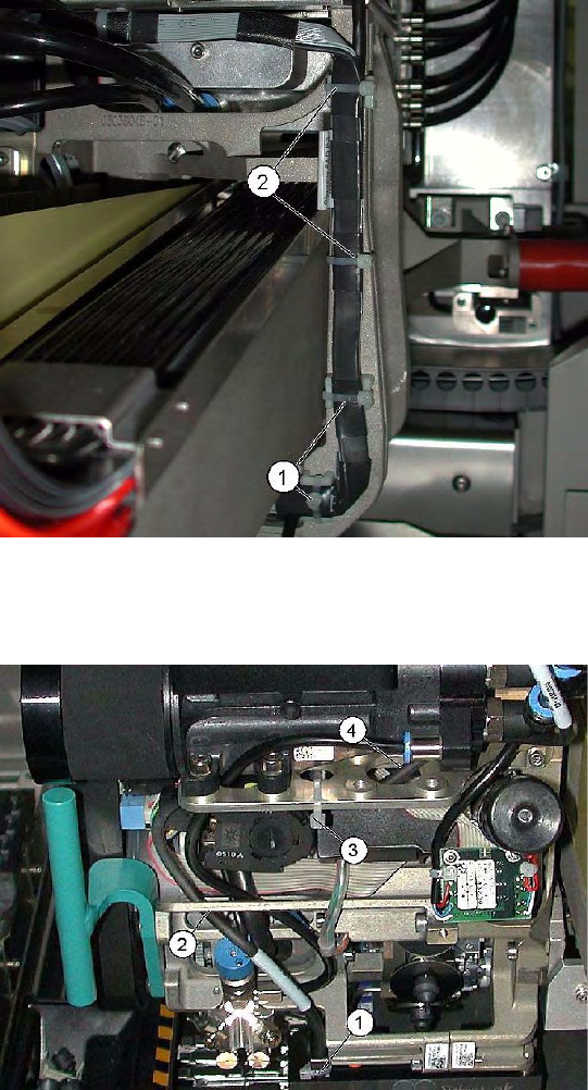
4.5.21.2 X Gantry Cable Routing
4.5.21.3 Component Sensor Cable Routing
Avoid damage from the Y gantry.
Make sure that the X gantry cables do not touch
the Y gantry.
4 cables ties (1), (2) protect the cables from
damage caused by the Y gantry.
Always use small cable ties, which do not rub
against the gantry.
Avoid loose cables.
The connection cables for the component sensor
must be fixed with a cable tie near to the press-fit
connection, as shown at (1).
The cable is run through the frame openings (2)
and (4).
The cable is held by a cable tie at (3).
Service Work
Checking the Cable Routing C&P12 Placement Head
Service Manual SIPLACE D4
195
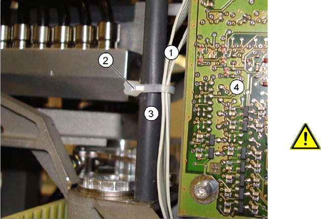
4.5.21.4 Running the Valve Positioning Drive Cables
Avoid loose cables.
The diagram shows the board support to the side
of the placement head and the illumination board
(4) on the component camera.
The connection cables for the valve positioning
drives (1) of the reject and placement circuits need
to be fixed at the bolt of the board holder (3) with a
cable tie (2).
CAUTION: Wrap insulating tape
around bare bolts
If the bolts are not already covered with
a plastic hose, as shown here, wrap
insulating tape around the fixture point.