80S-2080F480F5.pdf - 第116页
2 Introduction and Ba sic Concepts SIPLACE 80S-20/F4/F5 User Manual 2.4 Brief Description and Principles of the User Interface 05/99 I ssue from Software Version SR.405.xx 2 - 32 2.4.2 T he Mode Menu During placemen t, t…
SIPLACE 80S-20/F4/F5 User Manual 2 Introduction and Basic Concepts
05/99 Issue from Software Version SR.405.xx 2.4 Brief Description and Principles of the User Interface
2 - 31
2.4 Brief Description and Principles of the
User Interface
2.4.1 Main View
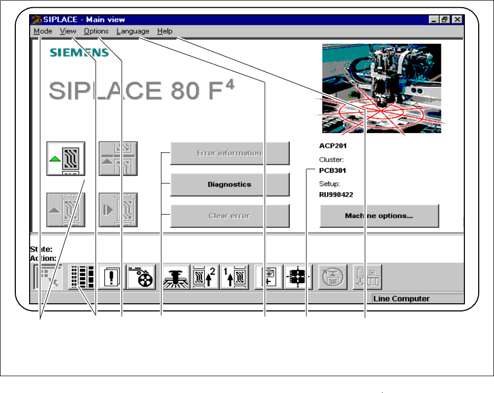
The main view displays to the operator operating states, central settings and options of the machine. From the
main view the operator can control the basic functions of the machine (see Fig. 2.4.1). Central settings, func-
tions and options can be processed or implemented, depending on the user’s authorization level. You can
return directly to the main view from any other view.
Fig. 2.4.1 Main view
- Key to Fig. 2.4.1
1 The Mode menu 2 The View menu with button bar
3 The Options menu 4 Troubleshooting and Diagnostics buttons
5 The Language menu 6 Display box
7 The Help menu
1 3 2 5 4 6
7
2 Introduction and Basic Concepts SIPLACE 80S-20/F4/F5 User Manual
2.4 Brief Description and Principles of the User Interface 05/99 Issue from Software Version SR.405.xx
2 - 32
2.4.2 The Mode Menu
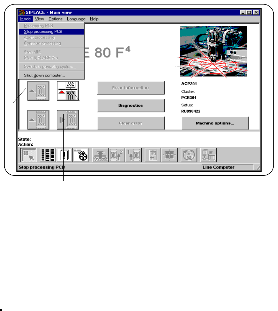
During placement, the operator has access to various options for operating the machine in the main view.
Fig. 2.4.2 Using the main view
- Key to Fig. 2.4.2
1 Process 2 Continue processing
3 Abort processing 4 Stop processing
2.4.2.1 Stop Processing
You can stop the process in order to execute Single functions, for example.
Click on this symbol.
The process will stop as soon as the PCB on the conveyor has been completed.
The color of the "Process“ icon changes to green.
1 3 2 4

SIPLACE 80S-20/F4/F5 User Manual 2 Introduction and Basic Concepts
05/99 Issue from Software Version SR.405.xx 2.4 Brief Description and Principles of the User Interface
2 - 33
2.4.2.2 Process
Click on this symbol to continue placement after stopping the processing (placement) of the PCB, e.g. in order
to change between Single functions.
The color of the "Stop processing" symbol changes to red.
2.4.2.3 Abort Processing
The symbol lights up red.
Click on this symbol to abort process of a PCB, e.g. after a fatal error message. You will be asked to confirm
the command.
PLEASE NOTE
An error message on the status bar is automatically acknowledged.
2.4.2.4 Continue Processing
The symbol lights up green.
Click on this symbol to continue processing and complete a PCB despite a fatal error message.
PLEASE NOTE
An error message on the status bar is automatically acknowledged.
2.4.2.5 Switching to the operating system (user class: line engineer or above)
Use this option to switch to the Windows user interface. From there, you can then return to the SIPLACE user
interface.