80S-2080F480F5.pdf - 第533页
SIPLACE 80S-20/F4/F5 User M anual 9 Maintenance 05/99 Issue from Software Version SR.405.xx 9.6 IC Head (SIPLACE 80F4/F5) 9 - 67 9.6.4 Cleanin g the Frict ion ring of the D Drive Unit Move th e IC hea d to the se rvice p…
9 Maintenance SIPLACE 80S-20/F4/F5 User Manual
9.6 IC Head (SIPLACE 80F4/F5) 05/99 Issue from Software Version SR.405.xx
9 - 66
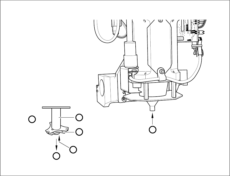
Fig. 9.6.3 Maintenance of the o-ring of the pick-up star
- Key to Fig. 9.6.3
1 Magnified view of the pick-up star
2 IC-head sleeve
3 The pick-up star remains screwed into the sleeve.
- Sequence of work in Fig. 9.6.3
A Return the nozzle to the nozzle changer (
Gantry 1 functions
).
B Clean the o-ring with alcohol and grease it sparingly with Unisilkon L250L.
1
1
A
B
2
3
SIPLACE 80S-20/F4/F5 User Manual 9 Maintenance
05/99 Issue from Software Version SR.405.xx 9.6 IC Head (SIPLACE 80F4/F5)
9 - 67
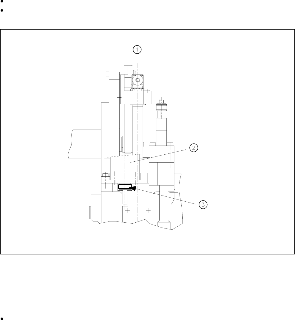
9.6.4 Cleaning the Friction ring of the D Drive Unit
Move the IC head to the service position.
Clean the visible area at the circumference of the friction ring (see Fig. 9.6.4) with alcohol and a clean
cloth.
Fig. 9.6.4 Cleaning the friction ring of the d drive unit
- Key to Fig. 9.6.4
1 View of the IC head in the direction of PCB transport
2 D axis motor
3 Friction ring - Clean the outside with alcohol. (The friction ring is covered with an angle bracket.)
Switch the machine on and rotate the d axis as described below:
Hold the cloth dampened with alcohol against the circumference of the friction ring:
Select the IC head functions menu in the Gantry 1 functions menu and click on the Turn D axis button.
(Whenever you click on this option, the friction ring is also turned through 90°).
Clean in this way the entire circumference of the friction wheel.
9 Maintenance SIPLACE 80S-20/F4/F5 User Manual
9.6 IC Head (SIPLACE 80F4/F5) 05/99 Issue from Software Version SR.405.xx
9 - 68
9.6.4.1 Replacing the Silencer
NOTE
Contamination of the filter in the silencer may lead to faults in the vacuum generation unit.
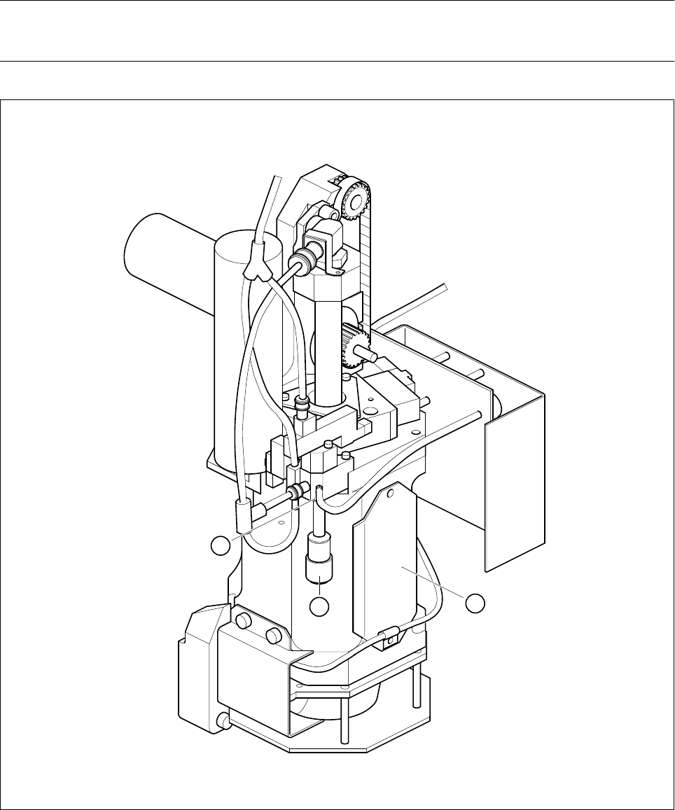
Fig. 9.6.5 Replacing the silencer filter of the vacuum generator
- Key to Fig. 9.6.5
1 IC head
2Silencer cap
3 Vacuum generator
2
3
1