80S-2080F480F5.pdf - 第486页
9 Maintenance SIPLACE 80 S-20/F4/F5 User Manual 9.3 Machine Base 05/99 Issue f rom Software Version SR.405.xx 9 - 20 9.3.2.3 Cleaning the Dust Filter of the Control Unit l Control unit of ’PCB Handling’, right-hand side …
SIPLACE 80S-20/F4/F5 User Manual 9 Maintenance
05/99 Issue from Software Version SR.405.xx 9.3 Machine Base
9 - 19
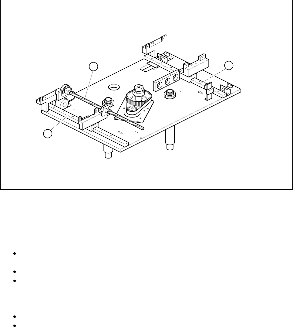
Fig. 9.3.1 Maintaining the width adjustment device (PCB transport modules not shown)
- Key to Fig. 9.3.1
1 Spherical rotating liners for width adjustment
2 Flat guideways
l Cleaning and oiling the recirculating ball screws of the width adjustment device
Clean thoroughly the recirculating ball screws of the width adjustment device by pulling a cloth soaked
in alcohol through each of the threads in turn.
If necessary use a brush soaked in alcohol. The bearings should not come into contact with alcohol.
After drying, apply a light and even film of watchmaker’s oil to the circumference of the spherical rotat-
ing liners.
l Cleaning and greasing the flat guideways of the width adjustment
Rub the slide faces of the flat guideways with a lint-free cloth soaked in alcohol.
Grease these slide faces evenly and sparingly with Staburags N12. Remove excess grease.
1
2
2

9 Maintenance SIPLACE 80S-20/F4/F5 User Manual
9.3 Machine Base 05/99 Issue from Software Version SR.405.xx
9 - 20
9.3.2.3 Cleaning the Dust Filter of the Control Unit
l Control unit of ’PCB Handling’, right-hand side
Undo the four recessed head screws fastening the dust filter frame.
Clean the dust filter using a vacuum cleaner.
l Control unit of ’PCB Handling’, left-hand side
Take off the dust filter frame fit to the control unit.
Clean the dust filter.
9.3.3 Component Tables
For all maintenance work on the components tables the feeder modules will have to be removed.
NOTE
The allocations of component, track number and module type are predefined for the placement of a batch of
components. If the components table is not being maintained in conjunction with a conveyor change or setting
up the machine, these allocations must be retained. If you do not have a data printout for the allocations of
track and feeder module (for example, ’Track X, 8 mm electric’) make a note of the allocations when you
remove the modules. You should also leave the tape rolls with the components in their respective roll compart-
ments so that you can refit them correctly later. To prevent the modules getting mixed up, we recommend you
first complete all of the maintenance work on one components table including refitting the modules before
starting on maintenance of the next components table.
9.3.3.1 Removing Feeder Modules
Switch the machine off at the main switch and open the safety hoods.
Slide the placement heads by hand far enough into the board conveyor area for them not to be damaged
when the feeder modules are removed from the components table. With the SIPLACE 80S-20 pay atten-
tion to the minimum clearance of the gantries (anti-crash switch), particularly before switching the machine
back on.
Remove the tapes with the components from the feeder modules:
Here you should cut the tape as far forward as possible and then pull the tape towards the end of the mod-
ule and out.
Immediately you remove the module, write the track numbers on the module using a waterproof marker
pen. This will make reinstallation easier later.
Lift the feeder modules off the locating pins of the components table and set it down on a suitable, clean
surface outside the machine.
9.3.3.2 Cleaning the Components Tables
Remove all feeder modules from the components table, as described in the preceding section.
Clean the entire surface of the components table thoroughly with the vacuum cleaner.
SIPLACE 80S-20/F4/F5 User Manual 9 Maintenance
05/99 Issue from Software Version SR.405.xx 9.3 Machine Base
9 - 21
9.3.3.3 Cleaning the Feeder Modules, Clearing Loose Components
Remove the tapes and with the vacuum cleaner thoroughly clean the surface of the modules, particularly
the area of the tape guide.
9.3.3.4 Oiling the bearing surface for the feeder modules
The bearing surface should be lightly oiled every time a feeder module is changed.
Apply a small quantity of WD40 corrosion protection agent to a clean cloth and rub it over the module bear-
ing surface on the components table. Remove excess WD40 and replace the module in the track.
9.3.3.5 Maintenance of the Magnetic Strips and Bearing Surfaces of the Feeders
DANGER
Do not carry out any cleaning work with alcohol in the presence of naked lights or fire!
Caring for the magnetic strips
The feeder modules are removed from the components table (see Section 9.3.3.1).
NOTE
The compressed air distributor strip on the components table is used for connecting the bulkcase feeders.
This strip runs parallel to the board conveyor and has upward-pointing open nozzles. Make sure that the
nozzles do not get contaminated with oil or come into contact with grease. Grease, oil or dirt will lead to
feeder malfunctions or components on the feeder will be rendered unusable.
Cover the nozzles of the distributor strip with insulation tape, for example.
Check the surface of the components table magnetic strips for damage or scratches.
If necessary, work over the surface with an oilstone and then wipe the magnetic strip with a cloth soaked in
alcohol.
Apply a small quantity of WD40 corrosion protection agent to the magnetic strip with a cloth.
Cleaning and oiling the bearing surfaces of the feeders
Wipe the bearing surfaces of the feeder modules on the components table with a cloth soaked in alcohol.
Apply a small quantity of WD40 corrosion protection agent to the magnetic strip with a cloth.