80S-2080F480F5.pdf - 第644页
11 Station Extensions/Options SIPLACE 80S-20/F4/F5 User Manual 11.5 Flip-Chip Vision Module 05/99 Issue from Software Version SR.405.xx 11 - 28
SIPLACE 80S-20/F4/F5 User Manual 11 Station Extensions/Options
05/99 Issue from Software Version SR.405.xx 11.5 Flip-Chip Vision Module
11 - 27
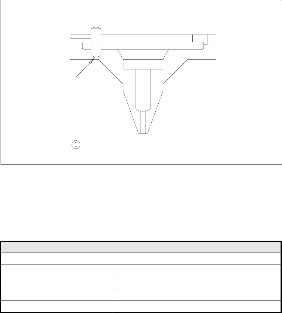
11.5.3 Type 412 Nozzle for Flip-Chip
Fig. 11.5.3 Type 412 nozzle
- Key to Fig. 11.5.3
1 Underside of pin blackened
11.5.3.1 Technical Data
Type 412 Nozzle for Flip-Chip
Outside diameter 1.8 mm
Suction diameter 1.0 mm
Suction area
0.8 mm
2
Color coding None
Material Black PETP Ertalyte
11 Station Extensions/Options SIPLACE 80S-20/F4/F5 User Manual
11.5 Flip-Chip Vision Module 05/99 Issue from Software Version SR.405.xx
11 - 28

SIPLACE 80S-20/F4/F5 User Manual 11 Station Extensions/Options
05/99 Issue from Software Version SR.405.xx 11.6 Ceramic Substrate Centering
11 - 29
11.6 Ceramic Substrate Centering
11.6.1 General Comments
Ceramic substrate centering can be carried out both mechanically and optically.
With optical centering the fiducials can be recognized with normal lighting or with oblique lighting.
11.6.2 Possible Centering Methods
The following methods of centering ceramic substrates can be added to the machine data (real.ma) under
Transport type
.
11.6.3 Mechanical Centering
11.6.3.1 General Comments
Ceramic substrate centering is used for holding ceramic substrates securely in the x and y directions and with
the material being protected. Ceramic substrates can also be mounted right up to the edge of the substrate.
11.6.3.2 Changing from Ceramic Substrate to Board
Disconnect the pneumatic line and the electrical connecting line (see item
1
in Fig. 11.6.1).
Remove the ceramic substrate centering device (see item
2
in Fig. 11.6.1).
Remove the base of the ceramic substrate centering device (see item 3 in Fig. 11.6.2).
Remove the three clamping devices (see item 4 in Fig. 11.6.1), fitting the standard guide in their place.
Fit the retainer brackets (see item 5a and 5b in Fig. 11.6.1).
Set the size of the board (see item 6 in Fig. 11.6.1).
Edit the transport type in the machine data (see Table in Section 11.6.2) using the SITEST program.
For operation under ’Single functions’ see also Section 4.4 of this user's manual.
Transport type Centering
4 Mechanical substrate centering with normal lighting
5 Oblique lighting only, with y clamping
6 Mechanical substrate centering with oblique lighting