80S-2080F480F5.pdf - 第353页
SIPLACE 80S-20/F4/F5 User M anual 5 Vision Func tions 05/99 Issue from Software Vers ion SR.405.xx 5.6 Test Comp onent Line en gineer 5 - 121 – c entre of the lea d, centre me asureme nt, for PL CC, SOJ, for exam ple – m…
5 Vision Functions SIPLACE 80S-20/F4/F5 User Manual
5.6 Test Component 05/99 Issue from Software Version SR.405.xx
5 - 120 Line engineer
Resolution in the integration direction
Select this resolution in order to optimize the measuring times at the revolver head.
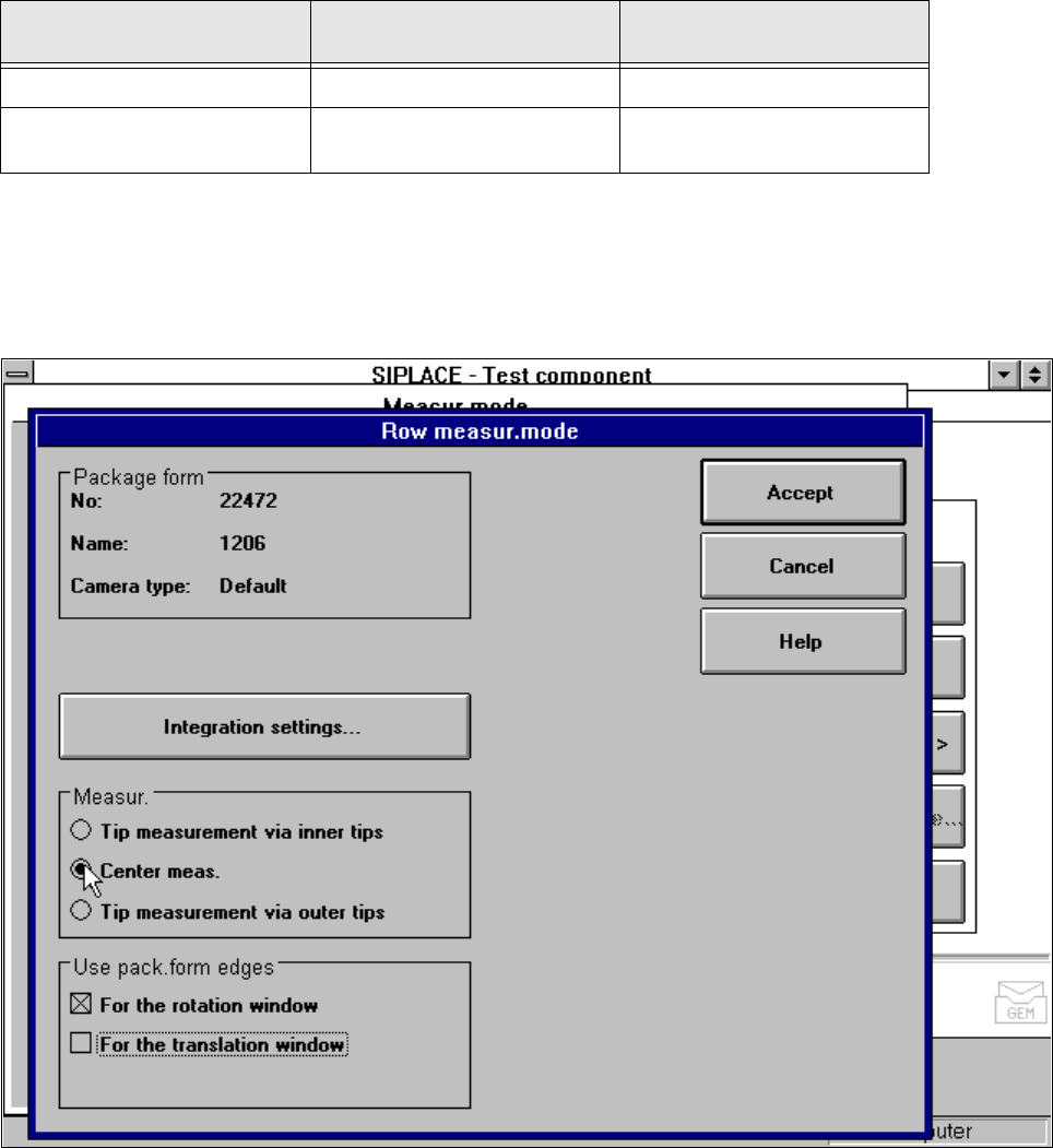
5.6.4.17 ’Row’ Measuring mode
Click on the ‘Setting’ field in the
Row measuring mode
menu to call up the following menu:
Fig. 5.6.37
Measuring mode
option,
Row measuring mode
menu
This menu is used to
– specify the lead measuring method.
– use the package form edges for the rotation windows and/or translation windows.
Measurement
If the inner lead tips are mapped better that the outer tips, for example if a shiny lead is bent upwards slightly,
you can select one of the following options:
– measuring the tips via the inner tips of the leads, for bases, for example
Resolution
in the measuring direction
Resolution
in the integration direction
Small components very high very high
Large components with a
measuring step to follow
high medium
SIPLACE 80S-20/F4/F5 User Manual 5 Vision Functions
05/99 Issue from Software Version SR.405.xx 5.6 Test Component
Line engineer 5 - 121
– centre of the lead, centre measurement, for PLCC, SOJ, for example
– measuring the tips via the outer tips of the leads, for QFP, SOT, SO, for example
Use package form edges
–
for rotation windows
The package form edges can be used to optimally position the rotation windows. However, to do this, the
package form edge must be visible and it must not contain a row of leads (eg white plugs).
–
for translation windows
The package form edges can be used to optimally position the translation windows. However, to do this,
the package form edge must be visible and it must not contain a row of leads.
PLEASE NOTE:
Do not use measurement mode Row together with measurement mode Size.
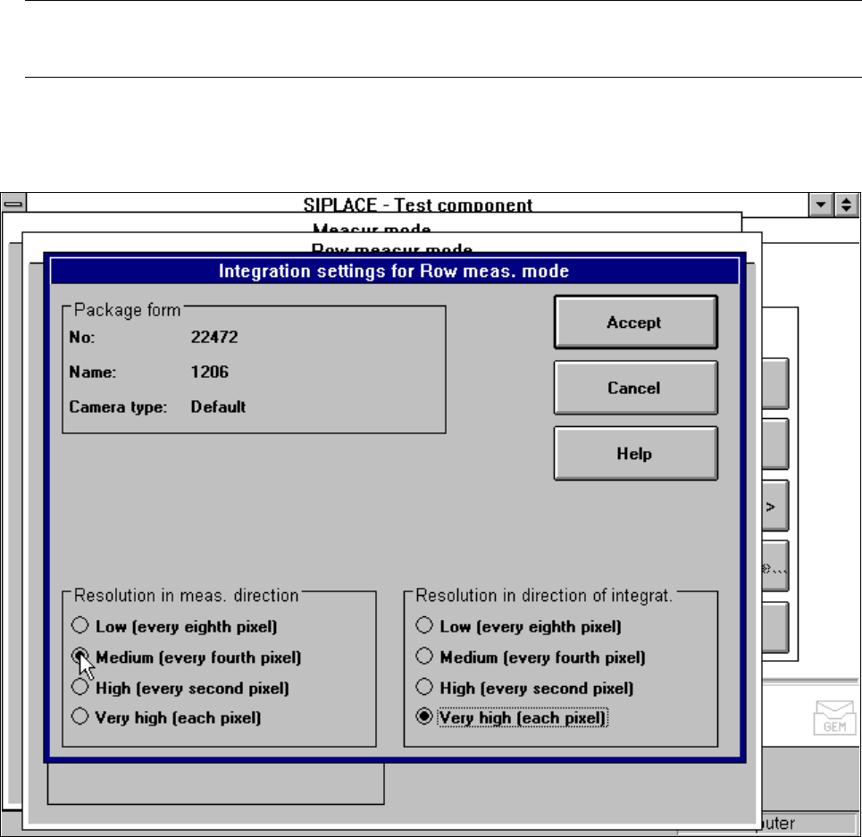
Integration settings
Once you have clicked on the ‘Integration settings’ field, the
Row measuring mode integration settings
menu will appear on screen.
Fig. 5.6.38 Measuring mode option, Row measuring mode integration settings menu
Measuring times can be reduced by lowering the resolution in the measuring or integration direction. How-
ever, you must ensure that the structure to be analysed has a sufficient number of pixels. Otherwise, the mea-
suring quality will be compromised. We recommend to choose the resolution ’High’ or ’Very high’.
5 Vision Functions SIPLACE 80S-20/F4/F5 User Manual
5.6 Test Component 05/99 Issue from Software Version SR.405.xx
5 - 122 Line engineer
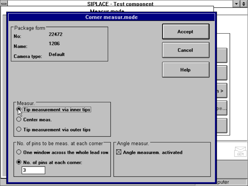
5.6.4.18 ‘Corner’ measuring mode
Click on the ‘Setting’ field in the ‘Corner’ measuring mode to call up the
Corner measuring mode
menu.
Fig. 5.6.39
Measuring mode
option,
Corner measuring mode
menu
This menu is used to
– specify the lead measuring method.
– select the number of leads to be measured at each corner.
– switch the angle measurement on or off.
Measurement
If the inner lead tips are mapped better that the outer tips, for example if a shiny lead is bent upwards slightly,
you can select one of the following options:
– measuring the tips via the inner tips of the leads, for bases, for example
– centre of the lead, center measurement, for PLCC, SOI, for example
– measuring the tips via the outer tips of the leads, for QFP, SOT, SO, for example
Number of leads to be measured at each corner
If the lead no longer stands out well from the background, in the case of white plugs, for example, use this
option to specify the number of leads to be measured. However, to do this, the component must be fully
described in the line computer (FDC). In this case, there are no further lead measuring steps.