80S-2080F480F5.pdf - 第500页
9 Maintenance SIPLACE 80 S-20/F4/F5 User Manual 9.3 Machine Base 05/99 Issue f rom Software Version SR.405.xx 9 - 34 9.3.6 Emptying the Reject s Cont ainer for the IC Head (SIPLA CE 80F 4 / F 5 ) As regar ds the po sitio…

SIPLACE 80S-20/F4/F5 User Manual 9 Maintenance
05/99 Issue from Software Version SR.405.xx 9.3 Machine Base
9 - 33
NOTE
If, despite changing the filter cartridges, the manometers still do not show 5.0 bar and 2.3 bar this will be
due to other reasons, as described in Section 9.3.5.1 on page 9 - 29.
Reinsert the cover plate.
9 Maintenance SIPLACE 80S-20/F4/F5 User Manual
9.3 Machine Base 05/99 Issue from Software Version SR.405.xx
9 - 34
9.3.6 Emptying the Rejects Container for the IC Head (SIPLACE 80F
4
/
F
5
)
As regards the position of this rejects container at the machine base, please refer to Fig. 9.3.6.
The machine is switched off at the main switch and the sliding safety hoods are open.
Check first whether the z axis (sleeve) is in its top end position. If it is not, this indicates a fault. You should
inform Siemens’ SMD service department.
Move the gantry away from the rejects container by hand. Only hold the gantry and never the placement
head.
Lift the rejects container vertically upwards and off the magnetic disk, making sure that no components
drop into the working area of the machine.
Place the empty container back in the center of the magnetic plate.
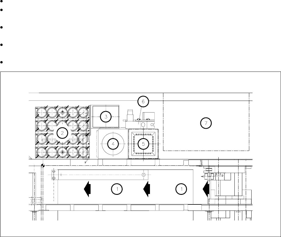
Fig. 9.3.6 Emptying the rejects container for the IC head, position at the machine base
- Key to Fig. 9.3.6
1 Direction of PCB transport
2 IC head nozzle changer
3 Rejects container for IC head
4 Flip-chip sensor
5IC sensor
6 Coplanarity module
7 Wafflepack changer
SIPLACE 80S-20/F4/F5 User Manual 9 Maintenance
05/99 Issue from Software Version SR.405.xx 9.3 Machine Base
9 - 35
9.3.7 Cleaning the IC Head Nozzle Changer (SIPLACE 80F
4
/F
5
)
NOTE
Carry out maintenance of the nozzle changer whenever possible in conjunction with maintenance or inspec-
tion of the nozzles since for this work the nozzles have to be removed from the nozzle changer and afterwards
put back in their correct allocations.
The position of the nozzle changer in the machine base is shown in Fig. 9.3.6.
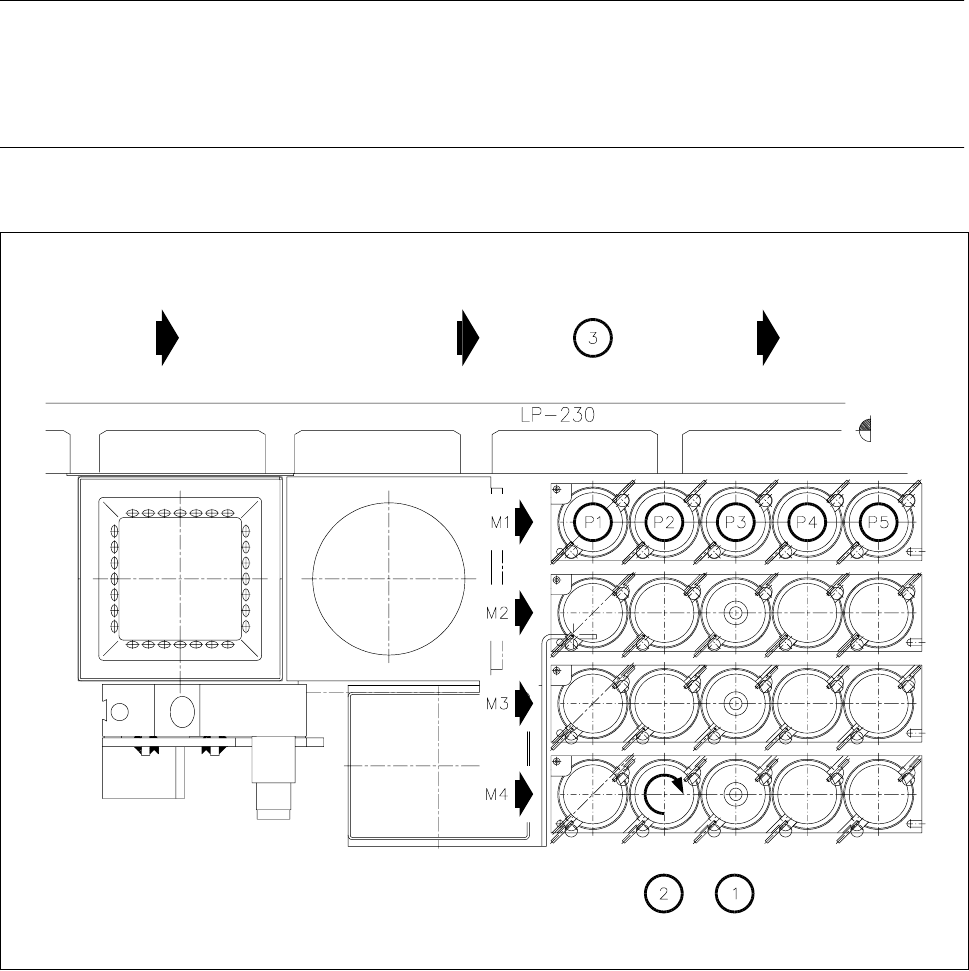
Fig. 9.3.7 Maintenance of the nozzle changer, allocations of nozzle to garage number
- Key to Fig. 9.3.7
1 Cleaning the locating holes
2 Direction of rotation for unlocking the nozzle for removal
3 Direction of PCB transport
M1 - M4 Magazine number
P1 - P5 Nozzle garage number