80S-2080F480F5.pdf - 第364页
5 Vision Functions SIP LACE 80S-20/F4/F5 Us er Manual 5.7 Guidelines for Describi ng Package Forms 05/99 Issue from Software Version SR.405.xx 5 - 132 Line en gineer 5.7.4 T est Package Form - V isual Represent ation / P…
SIPLACE 80S-20/F4/F5 User Manual 5 Vision Functions
05/99 Issue from Software Version SR.405.xx 5.7 Guidelines for Describing Package Forms
Line engineer 5 - 131
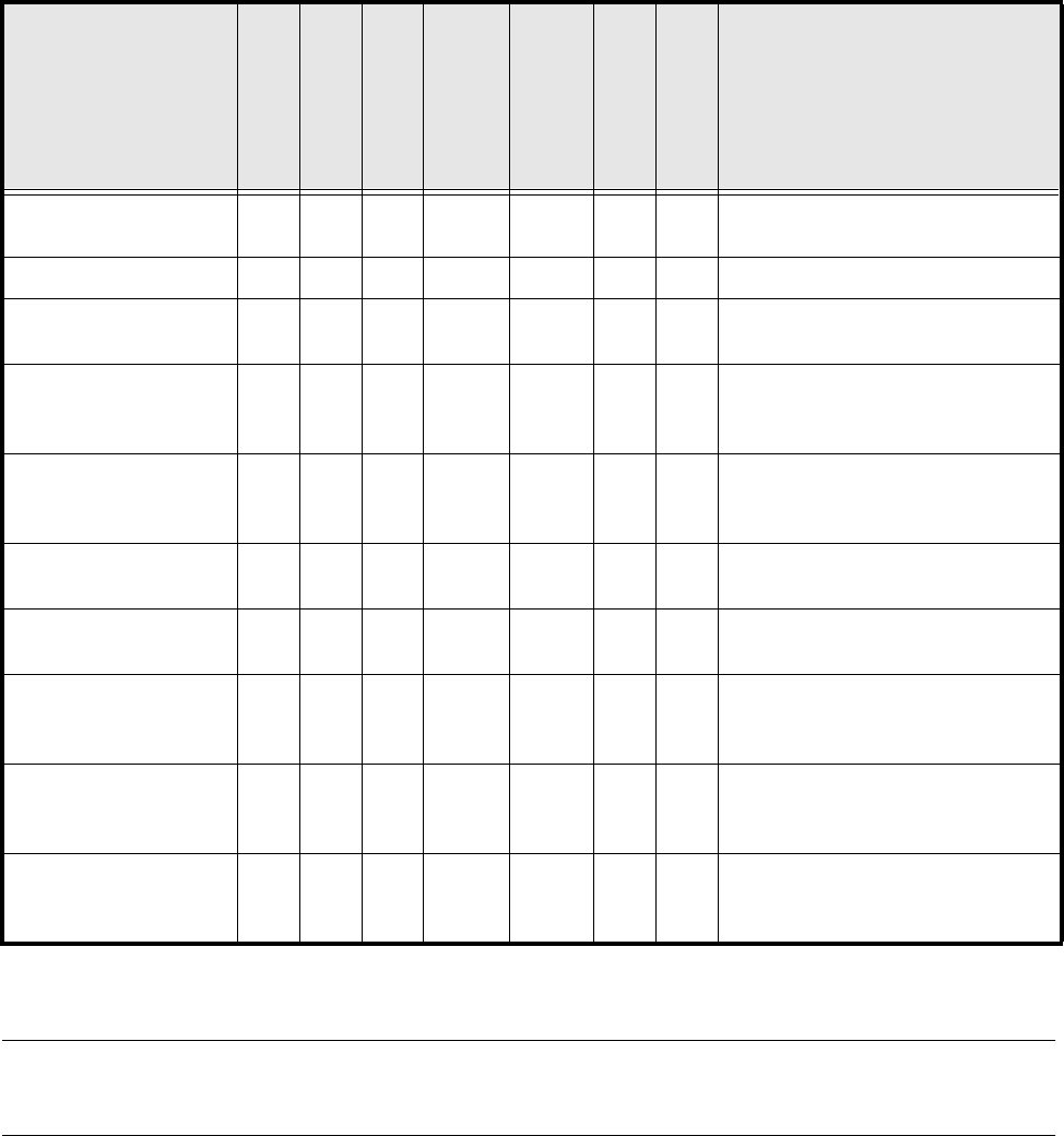
5.7.3 Shapes and possible measuring methods for rough (G) and fine
centering (F)
If one or more of the results are outside the tolerance,
the component will not be inserted.
If the component cannot be centered correctly, additional measuring methods may be omitted. You should,
however, carry out all the rough centering steps since these reduce the size of the measuring window.
– In the ’Test component’ menu, the components are optically centered in the individual measuring steps, via
the ’Check component’ function, but the results are not output.
– In the ’Test component’ menu, the components are optically centered in the individual measuring steps, via
the ’Measure component’ function, but the results are not output.
– If the components are larger than 32 mm x 32 mm, a multiple measurement will be carried out automati-
cally in the vision system.
Design
SIZE
ROW
CORNER
Lead :
Combined
Lead Separate
Evaluation window
Grid
Ball
Result of the last measuring step
PDC without lead G/F
∆X, ∆Y, (∆φ), Component length
width, (quality)
PDC rounded image G/F F Angular tolerance
Small FDCs, e.g.
2 leads
G/F F
∆X, ∆Y, (∆φ), Component length
width, (quality)
FDC, regular with short
rows of PINs
GF
Four-
sided
F
Four-
sided
F
Max. deviation from the spacing:
∆X, ∆Y, ∆φ,
(quality)
FDC, regular with long
rows of PINs
GF
Four-
sided
F
Four-
sided
F
Max. deviation from the spacing:
∆X, ∆Y, (∆φ),
quality
FDC irregular with short
rows of PINs
G(G)F F
∆X, ∆Y, number of PINs (quality)
max. deviation from the spacing
FDC, irregular with long
rows of PINs
G(G)F F
∆X, ∆Y, number of PINs (quality)
max. deviation from the spacing
FDC, irregular with one
row of PINs, several
PIN models or spacings
GG F
∆X, ∆Y, (∆φ), standardized lead devi-
ation (quality)
Number of PINs, secondary offset
FDCs with circular seg-
ment PIN arrangements
(G) G F
∆X, ∆Y, (∆φ), standardized lead devi-
ation (quality)
Number of PINs, secondary offset
BGA, flip-chip G G F
∆X, ∆Y, (∆φ), spacing,
angle,
quality)
Tab. 5.7.1 Component measuring methods
5 Vision Functions SIPLACE 80S-20/F4/F5 User Manual
5.7 Guidelines for Describing Package Forms 05/99 Issue from Software Version SR.405.xx
5 - 132 Line engineer
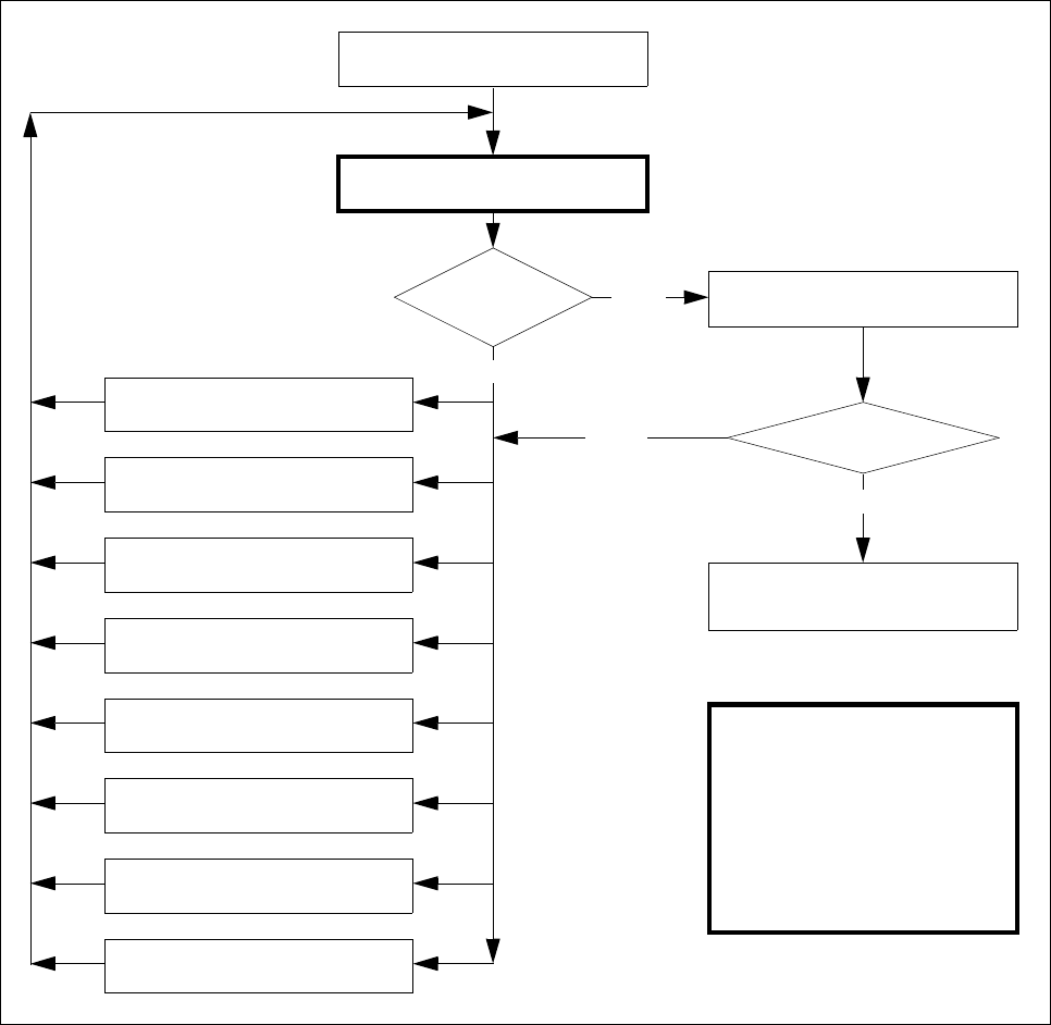
5.7.4 Test Package Form - Visual Representation / Programming Mea-
surement Types
– In the ’Test component’ menu, a component is picked up and then moved to the camera and mapped in its
0° position. The component is displayed with respect to its insertion angle at the revolver head of the S-20/
F
4
/F
5
.
Fig. 5.7.5 Order in which package forms are programmed at the station
Important note:
The manipulation of
components at the station
must remain the exception,
rather than the rule.
In general, only a few components
have to be changed.
Are the results
constant?
No
Measure component
Error
Yes
Repeat the measurement
and view the results
Yes
Assemble component
several times
8. Modify the contrast sensitivity
(Program table)
7. Modify pin/ball
dimensions
6. Modify pin/ball contrast
5. Modify component dimension
4. Modify measuring modes and
measuring
3. Modify lighting
2. Display component
1. Handling error:pick-up angle,
nozzle type, component on nozzle,
No
Measure component
„RETURN“ next measurement
SIPLACE 80S-20/F4/F5 User Manual 5 Vision Functions
05/99 Issue from Software Version SR.405.xx 5.7 Guidelines for Describing Package Forms
Line engineer 5 - 133
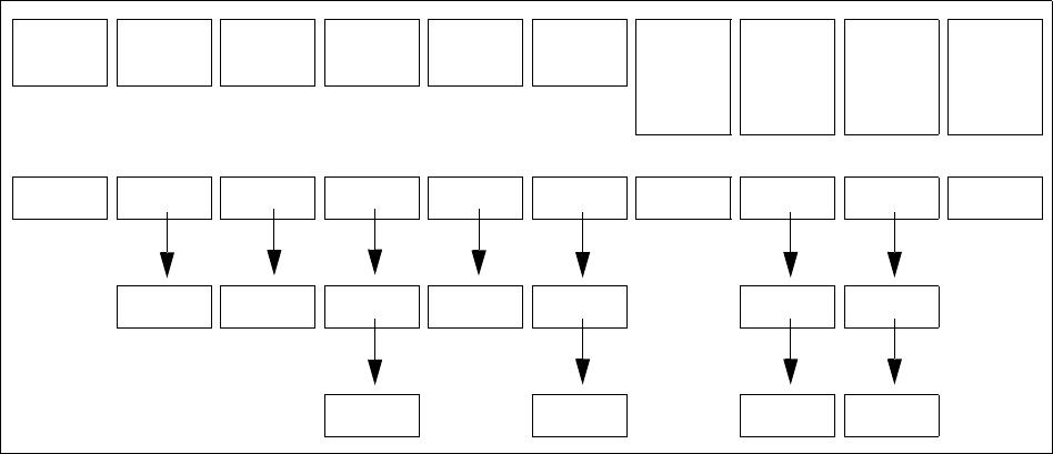
5.7.5 Parameters for the Measuring Methods
Possible sequences of measuring methods
It is also possible to program other sequences, such as corner followed by lead or lead only. Such combina-
tions are very unusual, however. If the component is defined in the package form editor, then the measuring
methods will be pre-assigned. However, in some cases it may be necessary to modify the measuring methods
at the station so that the component can also be optically centered.
The results from the last measurement are always saved. The previous measurement is used as a rough cen-
tering step for the next measurement and thus helps to reduce the measuring window.
The more measuring methods are used, the longer the entire measuring procedure will be. A large number of
measuring methods for a component can delay the head cycle. This applies to the revolver head in SIPLACE
80S-20, 80F
4
, and 80F
5
automatic placement machines, in particular.
PDC/
FDC
FDC FDC FDC FDC FDC Flip-
Chips
S15
Flip-
Chips
F
3,4
/S20
F
5
Ball
Grid
Array
Bare
Dies
Size Size Size Size Row Row Size Size Size Size
Lead Corner Corner Corner Corner Grid Grid
Lead Lead Ball Ball
T
ab. 5.7.2 Possible sequences of measuring methods