80S-2080F480F5.pdf - 第726页
17 Nozzle Overview SIPLACE 80 S-20/F4/F5 User Manual 17.1 Nozzle Contour Diagrams 05/99 Issue from Software Version SR.405.xx 17 - 6 17.1.2 Represent ation of a Nozzle Contou r Diagram Y ou ca n obtain the fol lowing i n…
SIPLACE 80S-20/F4/F5 User Manual 17 Nozzle Overview
05/99 Issue from Software Version SR.405.xx 17.1 Nozzle Contour Diagrams
17 - 5
17.1.1.3 Nozzle and Nozzle Contour
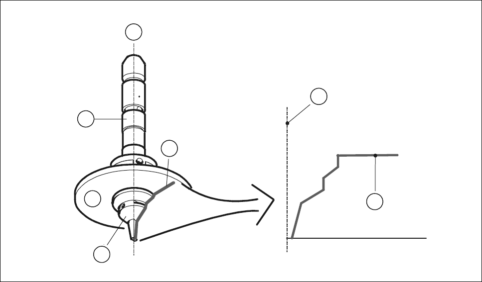
Fig. 17.1.3 ’Representation of the nozzle contour’ shows the relation between the nozzle and the nozzle con-
tour. The contour of the nozzle is depicted in the nozzle contour diagram.
Fig. 17.1.3 Representation of the nozzle contour
- Key to Fig. 17.1.3
1 Center of the nozzle
2 Nozzle contour
3Nozzle
4 Encoder disk
5 Segment
1
2
1
2
4
5
3
17 Nozzle Overview SIPLACE 80S-20/F4/F5 User Manual
17.1 Nozzle Contour Diagrams 05/99 Issue from Software Version SR.405.xx
17 - 6
17.1.2 Representation of a Nozzle Contour Diagram
You can obtain the following information from a nozzle contour diagram:
- Placement shadow in [mm]
- Components height difference in [mm]
NOTE
The placement shadow is defined as the distance required between two components when they are
inserted and taking the height difference into account.
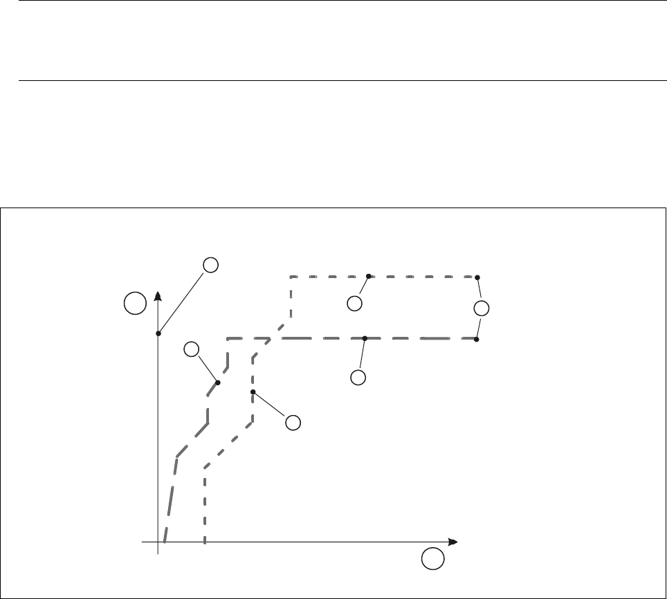
A nozzle contour diagram depicts all of the nozzle contours of a nozzle type.
As an example, Fig. 17.1.4 ’Representation of multiple nozzle contour diagrams’ shows two nozzle contours in
one diagram.
Fig. 17.1.4 Representation of multiple nozzle contour diagrams
- Key to Fig. 17.1.4
1 Components height difference in [mm] 2 Placement shadow in [mm]
3 Center of nozzle 4 Nozzle contour of nozzle B
5 Nozzle contour of nozzle A 6 Encoder disk of nozzle B
7 Encoder disk of nozzle A 8 Outside edge of encoder disk
4
1
3
7
6
8
5
2
SIPLACE 80S-20/F4/F5 User Manual 17 Nozzle Overview
05/99 Issue from Software Version SR.405.xx 17.1 Nozzle Contour Diagrams
17 - 7
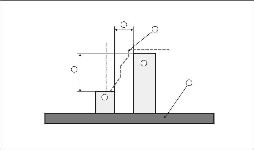
The following diagram shows the correlation between the values for the placement shadow and the compo-
nent height difference.
Fig. 17.1.5 Correlation between components height difference and placement shadow
- Key to Fig. 17.1.5
1 Components height difference 2 Placement shadow
3 Nozzle contour from diagram 4 PCB
5 Component 1 6 Component 2
Component 1 can now be inserted with the selected nozzle as close to component 2 as the height difference
of the two components permits.
1
2
3
4
5
6