80S-2080F480F5.pdf - 第723页
SIPLACE 80S-20/F4/F5 User M anual 17 Nozzle Overview 05/99 Issue from Software Version SR.405.xx 17.1 Nozzle Contour Diagrams 17 - 3 17.1 Nozzle Contour Diagrams In the fol lowin g sectio n a descri ption is provided o f…
17 Nozzle Overview SIPLACE 80S-20/F4/F5 User Manual
05/99 Issue from Software Version SR.405.xx
17 - 2
SIPLACE 80S-20/F4/F5 User Manual 17 Nozzle Overview
05/99 Issue from Software Version SR.405.xx 17.1 Nozzle Contour Diagrams
17 - 3
17.1 Nozzle Contour Diagrams
In the following section a description is provided of current SIPLACE nozzle contour diagrams. You can use
these diagrams to check whether a specific nozzle is suitable for a particular placement task.
The nozzle contour diagrams provide a way of checking the components height difference and the placement
shadow for each placement task. This way you can determine how close to a plug, for example, a component
can be safely inserted without problems arising.
17.1.1 Definitions
17.1.1.1 Parameters Required
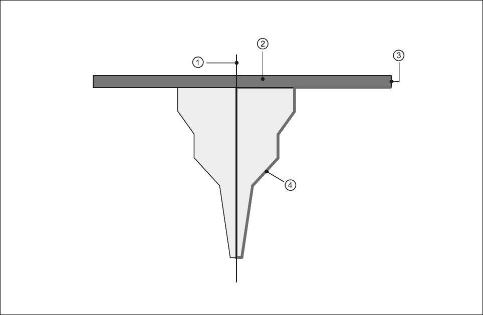
The following parameters will be presented in a nozzle contour diagram.
Fig. 17.1.1 General view of the nozzle
- Key to Fig. 17.1.1
1 Center of nozzle 2 Encoder disk
3 Outer edge of encoder disk 4 Nozzle contour
17 Nozzle Overview SIPLACE 80S-20/F4/F5 User Manual
17.1 Nozzle Contour Diagrams 05/99 Issue from Software Version SR.405.xx
17 - 4
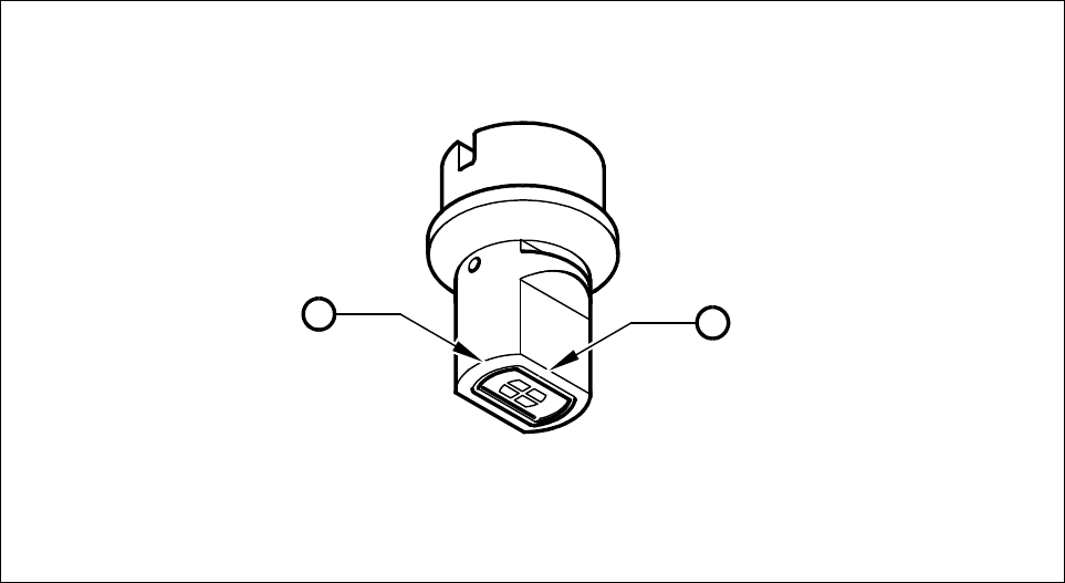
17.1.1.2 Long and Narrow Sides of the Nozzle
For every nozzle type (for example, 7xx) there are two nozzle contour diagrams. One diagram for the long
side and one diagram for the narrow side of the nozzles. In Fig. 17.1.2 the definition of the long and narrow
side of the nozzle is explained.
Fig. 17.1.2 Long and narrow side of the nozzle
- Key to Fig. 17.1.2
1 Long side of the nozzle
2 Narrow side of the nozzle
1
2