80S-2080F480F5.pdf - 第585页
SIPLACE 80 S20/F4/F5 User Manual 10 Component Handling 05/99 Issue from Software Version SR .405.xx 10.3 Component table, mobile 10 - 13 Key to Fig. 10.3. 1 (1) Comm unicatio n interfa ce co nnector (2) Power supply conn…
10 Component Handling SIPLACE 80 S20/F4/F5 User Manual
10.3 Component table, mobile 05/99 Issue from Software Version SR.405.xx
10 - 12
10.3.2 Undocking the component table
Fig. 10.3.2 Undocking the mobile component

SIPLACE 80 S20/F4/F5 User Manual 10 Component Handling
05/99 Issue from Software Version SR.405.xx 10.3 Component table, mobile
10 - 13
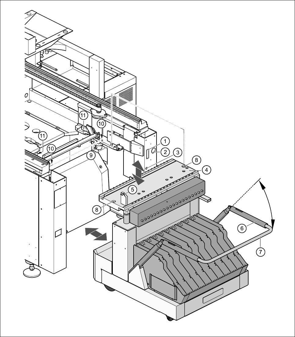
Key to Fig. 10.3.1
(1) Communication interface connector
(2) Power supply connector for the component table
(3) Compressed air connection
(4) Component table bed
(5) Button for raising and lowering the component table bed
(6) Actuating tube
(7) Fold-down bracket
(8) Holes for the centering pins
(9) Centering pins
(10) Contact surfaces for the slide rails of the component table
(11) Horizontal tensioners
Click on the PAUSE OPERATION icon in the BASIC VIEW menu.
The PCB in progress will be completed. The icons of the SINGLE FUNCTIONS menu will then be acti-
vated.
Click on the desired SINGLE FUNCTIONS GANTRY X icon (gantry 1 or 2).
Click on the GANTRY FUNCTIONS icon.
From this menu, click on the APPROACH SET-UP POSITION button.
The selected placement head will move across the PCB transport to prevent it being damaged when the
component table is changed.
Open protective cover of the selected gantry.
Open the side screens.
Open the horizontal tensioners (item 11)
Pull the two actuating tubes (item 6) towards you at the same time and lift up the bracket (item 7) to lock
the raised component table bed in its top end position.
Hold down the button (item 5) for raising the component table bed (item 4) until the component table bed
reaches its top end position.
Unplug the component table power cable (item 2).
Unplug the component table control cable (item 1).
Disconnect the compressed air supply (item 3).
Remove the component table.
10 Component Handling SIPLACE 80 S20/F4/F5 User Manual
10.3 Component table, mobile 05/99 Issue from Software Version SR.405.xx
10 - 14
10.3.3 Docking the component table
WARNING
Check that the placement head is outside the range of the component table.
CAUTION
When docking the component table, ensure that the table bed is in its top end position and the bracket (item 7)
is folded up.
Cut off the empty tapes for the feeder modules.
Make sure that the contact surface (item 10) for the component table bed is clean.
CAREFULLY push the component table into the placement system.
Connect the compressed air supply (item 3).
Plug in the control cable (item 1).
Plug in the power cable (item 2) for the component table.
Pull the two actuating tubes (item 6) towards you at the same time and then lower the bracket (item 7) in
order to be able to lower the component table bed.
Check that the centring holes in the component table bed lie precisely over the centering pins of the place-
ment system.
Hold down the button (item 5) until the component table bed reaches its top end position.
Release the button and the component table bed will descend.
Ensure that the centring pins engage in the centring holes in the component table bed and that the compo-
nent table bed is fully lowered.
Fold up the bracket (item 7) of the component table.
Lock the two horizontal tensioners (item 11).
Close the side screens and protective cover.
Press the Start button to start the placement system.