80S-2080F480F5.pdf - 第248页
5 Vision Functions SIP LACE 80S-20/F4/F5 Us er Manual 5.2 PCB Vision System 05/99 Issue f rom Software Version SR.405.xx 5 - 16 Line en gineer – up to 4 c amera inpu ts – two seri al interf aces (RS23 2 or R S422) and th…

SIPLACE 80S-20/F4/F5 User Manual 5 Vision Functions
05/99 Issue from Software Version SR.405.xx 5.2 PCB Vision System
Line engineer 5 - 15
5.2 PCB Vision System
The PCB vision system registers the precise position of the board by surveying fiducials and then determines
the offset along the x and y axes, the skew with respect to the direction in which the boards are transported,
and also the shear of the board. The PCB vision system also registers and evaluates reject fiducials (ink
dots).
5.2.1 System Description
The PCB vision system for PCB position recognition consists of
l the optical system for PCB position recognition
Each gantry has its own PCB position recognition system (5 - 5).
PLEASE NOTE:
PCB position detection is only carried out with gantry 1.
l the vision evaluation unit
Each machine accommodates in the control unit an evaluation unit for PCB and component position recog-
nition (see Fig. 5.1.4, Fig. 5.1.7 and Fig. 5.1.10).
The optical PCB position recognition system consists of a CCD camera (a SONY XC75) with integrated imag-
ing and illuminating optics. The field of view of the board module is 5.7 mm x 5.7 mm. A search area can be
programmed by size and position within the dimensions of the field of view. The imaging lens is a special mea-
suring lens which compensates for virtually all measuring errors resulting from warping of the board. The light-
ing is only switched on while fiducials are being registered.
The vision evaluation unit (MVS) is a single-board system which conforms with the VME standard. The hard-
ware consists of:
l the MVS motherboard with vision processor and interface connections
The rear side of the board accommodates
– the plug-in connections for the VME bus and
– the high-speed communications unit (HS
3
L).
On the front side of the board are the connection sockets for
– the screen
Machine PCB camera MVS evaluation unit
80S-20 (2 gantries) 2 1
80F
4
(1 gantry)
11
80F
5
(1 gantry)
11
Tab. 5.2.1

5 Vision Functions SIPLACE 80S-20/F4/F5 User Manual
5.2 PCB Vision System 05/99 Issue from Software Version SR.405.xx
5 - 16 Line engineer
– up to 4 camera inputs
– two serial interfaces (RS232 or RS422)
and the indicator LEDs for
– the CPU
– the vision processor
– the camera input
– the screen display.
The
RESET
and
CANCEL
switches are located beneath the indicator LEDs.
l the MVS camera interface (piggyback board) for up to four CCD cameras.
5.2.2 Technical Data
Camera model: SONY XC75
Number of pixels: Camera 768 (H) x 494 (V), Image 640 (H) x 484 (V)
Field of view: 5.7 mm x 5.7 mm
Illumination method: Incident light method (activated during measurement)
Image processing: Correlation principle, gray scale system
Screen: RGB monitor (VGA mode) 640 x 484 pixels in the station computer
Fiducials: Library memory for up to 255 fiducial definitions
5.2.3 Description of Functions
Before placement the location, skew and shear of the board is determined by the PCB vision system using the
position of the fiducials. Deviations from the setpoint values are then included in the calculation of the place-
ment positions of the components as corrections.
A board must have at least 2 fiducials if the system is to be able to detect deviations in the board position and
the skew of the board. The presence of 3 fiducials will furnish additional information concerning skew or
stretching of the board or of the board layout.
5.2.4 Sequence of Functions
Before a fiducial can be used for board recognition it must first be ’taught’ to the machine. In other words, the
fiducial structure parameters must have been saved in the PCB vision system for that pattern.
The fiducial structure can be taught using the PCB vision camera mounted on the gantry and the vision
program. The vision evaluation unit determines the significant fiducial structure parameters using digital
image processing methods.
Measurement takes place in two stages:
– 2-D pattern search (2-dimensional process) in the coarse grid and provisional determination of the
fiducial coordinates
– 1-D pattern search (1-dimensional process) for a precise determination of the position of the fiducials.
SIPLACE 80S-20/F4/F5 User Manual 5 Vision Functions
05/99 Issue from Software Version SR.405.xx 5.2 PCB Vision System
Line engineer 5 - 17
With the 2-D pattern search process the template window is divided into moxel areas. Moxels (
mo
saic pi
xel
s)
are pixel fields containing for example 16 x 16, 8 x 8 pixels and so on. The lower the pixel count the higher the
resolution and the lower the search speed.
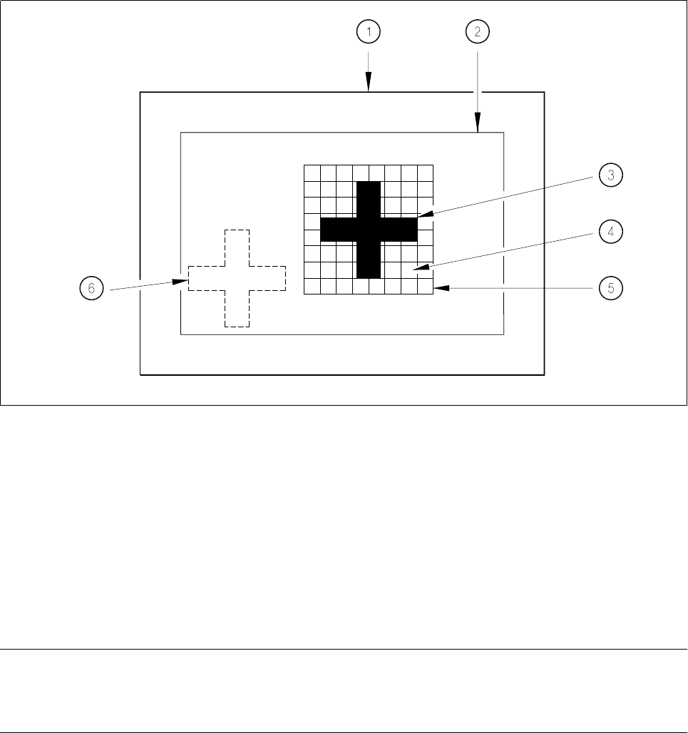
Fig. 5.2.1 Explanation of camera field of view, search area and template window
- Key to Fig. 5.2.1
1 Camera field of view 2 Search area, ≤ camera field of view
3 Reference fiducial (the fiducial is searched for in this area )
5 Template window 4 Moxel = pixel field, eg 16 x 16 pixels
(it contains the reference fiducial) 6 Fiducial which is to be searched for
The template window is moved over the search area in moxel steps. The gray scale values of each moxel of
the reference fiducial are calculated at this time. This reduced data structure will contain enough information
on the coarse structure and position of the reference fiducial.
NOTE
The search window should be as small as possible in order to keep the speed of searching high. On the other
hand the window should be large enough to allow the fiducial to be identified without ambiguity.
The 1-D pattern search procedure is used for precisely determining the pattern and position of the fiducial.
The fiducial image is broken up into rows and columns and the gray scale values in each row and column
added up. The next diagram illustrates this process using a double cross.