80S-2080F480F5.pdf - 第380页
5 Vision Functions SIP LACE 80S-20/F4/F5 Us er Manual 5.7 Guidelines for Describi ng Package Forms 05/99 Issue from Software Version SR.405.xx 5 - 148 Line en gineer . Fig. 5.7.1 1 Illumination parameters for components …
SIPLACE 80S-20/F4/F5 User Manual 5 Vision Functions
05/99 Issue from Software Version SR.405.xx 5.7 Guidelines for Describing Package Forms
Line engineer 5 - 147
5.7.8.2 Pseudo color representation
The pseudo color representation provides a powerful and objective assessment of the illumination, by repre-
senting a brightness value in a color.
A contrast of at least 4 color scales between the lead and body is required for a measurement. In the ‘Illumina-
tion’ menu of the package form manipulator, components are displayed in the pseudo color representation on
the station computer monitor.
5.7.8.3 Settings for Illuminating Components
The standard range of components includes chips (0603 to 2220), tantalum capacitors, Melf components,
PLCCs, QFPs, SOs, SOJs, TSOPs, ICs, power components, flip-chips, µBGAs and BGAs.
For the components which are listed below the GF interpreter in the station computer uses the default illumi-
nation parameters listed in Fig. 5.7.11:
– Chips (0603 to 2220)
– Tantalum capacitors (component bodies, non-reflective)
– Melf
– PLCC, QFP, SO, SOJ, TSOP, ICs, power ICs
– Flip-chips, µBGAs, BGAs
The special components include:
– Power transistors
– Plugs
– PLCC base
– Quartz timers
As a rule you will not need to change the illumination parameters for the components.
Color scale Brightness
white light
yellow
orange
red
brown
green
light blue
blue
violet
black dark
Tab. 5.7.5 Conversion table for the pseudo color representation at the 6x revolver head
5 Vision Functions SIPLACE 80S-20/F4/F5 User Manual
5.7 Guidelines for Describing Package Forms 05/99 Issue from Software Version SR.405.xx
5 - 148 Line engineer
.
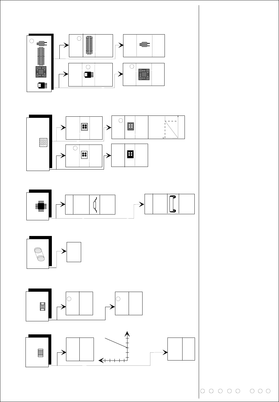
Fig. 5.7.11 Illumination parameters for components at the 6x revolver head camera (32x32)
D
iagram
f
or adjusting the illum
ination
of com
ponen
ts
C
hip
IC
M
elf
B
G
A
T
a
nta
lu
m
ca
pacitor
flat: 150
ste
ep:1
50
J-Lead
P
LC
C
flat: 70
stee
p: 140
C
eram
ic
B
G
A
flat: 0
steep
:
255
P
la
stic
B
G
A
080
5 an
d
la
rge
r
fla
t: 20
0
stee
p
: 120
0603
fla
t: 1
50
steep
: 2
00
G
e
neral
fla
t:
1
20
steep
: 1
50
flat: 2
5
5
stee
p: 1
3
0
fla
t: 2
00
steep
:
0
G
ullw
ing
S
O
,
S
O
T
,
T
S
O
P
Q
F
P
,
S
pe
cial com
p
one
nts
P
ow
er
tra
nsistor
flat: 25
5
stee
p: 15
0
P
LC
C
-
socket
fla
t: 0
- 30
s
te
ep
:1
50
-20
0
P
lug
flat:
0
ste
ep
: 15
0
-2
0
0
Q
ua
rtz
fl
a
t: 200
ste
ep
:1
20
-18
0
T
B
G
A
re
flect. b
od
y
fla
t: 2
00
stee
p: 0
T
B
G
A
dull
fla
t: 0
ste
il:1
50
-20
0
a
p
prox. 1
80
2
5
5
If n
e
cessa
ry,
u
se
th
e
L
U
T
b
elo
w
1
R
eflect.
body
fla
t: 25
5
ste
e
p
: 4
0
8
6
2
7
5
3
4
6
1
2
3
4
5
D
o not use fo
r reflective com
pon
ents.
U
se negative
ball contrast w
hen
m
apping the ball.
T
he description
m
ust only contain
the innerm
ost row
of balls. U
se nega
tive contrast.
It
m
ust be possible t
o insert the com
po
nents. T
he test m
u
st be carried out for each type.
7
T
h
e edge of the large cooling surface is extrem
ely irregul
ar on som
e types o
n account of the production m
ethod
s used.
I
f you are unsure, do not use it for the m
easurem
ent
U
p to P
LC
C
52 b
ase. M
ake sure th
at you are using the correct nozzle.
D
escribe as for a
B
G
A
, if necessary
.
8
D
escribe as f
or an F
D
C
. M
easu
ring m
ode: size+
le
ad
1
50
2
55
C
o
ntrast
g
ra
d
ua
tio
n

SIPLACE 80S-20/F4/F5 User Manual 5 Vision Functions
05/99 Issue from Software Version SR.405.xx 5.7 Guidelines for Describing Package Forms
Line engineer 5 - 149
5.7.8.4 Testing Illumination Settings
You can set the illumination parameters by calling the ’Illumination’ option (see Section 5.6.4.8, Page 5 - 105).
Using the 'Measure Component Option' you can then measure the component and check your settings with
the aid of the measurement results.
Proceed as follows to test your illumination setting:
Using the illumination values suggested in Fig. 5.7.11 carry out measurement. Measurement should run
through successfully.
For each level reduce the set brightness level by 50 %.
Measurement should run through successfully.
For each level raise the set brightness level by 50 %.
Measurement should run through successfully.
If you are not successful with the above procedure, proceed as follows:
Starting with the suggested illumination value, increase the brightness of each individual illumination level
for as long as measurement is still successful.
Find this upper limit value for each individual illumination level in turn.
Starting with the suggested illumination value, decrease the brightness of each individual illumination level
for as long as measurement is still successful. Find this lower limit value for each individual illumination
level in turn.
Determine the average value of the upper and lower limit values. This will be the optimum illumination
value.
Example of an illumination test:
– Settings from the diagram:
flat: 150
steep: 180
– Measure the component. Measurement is successful.
– Reduce setting values by 50%.
flat: 75
steep: 90
– Increase setting values by 50%.
flat: 225
steep: 255
– Measure the component. Measurement is successful.
– Reset the settings to the suggested values:
flat: 150
steep: 180
¬ optimum setting