80S-2080F480F5.pdf - 第355页
SIPLACE 80S-20/F4/F5 User M anual 5 Vision Func tions 05/99 Issue from Software Vers ion SR.405.xx 5.6 Test Comp onent Line en gineer 5 - 123 NOTE This value s hould only be modifie d for spec ial compo nents and plugs .…
5 Vision Functions SIPLACE 80S-20/F4/F5 User Manual
5.6 Test Component 05/99 Issue from Software Version SR.405.xx
5 - 122 Line engineer
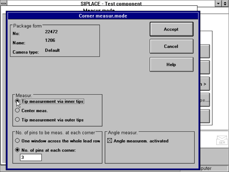
5.6.4.18 ‘Corner’ measuring mode
Click on the ‘Setting’ field in the ‘Corner’ measuring mode to call up the
Corner measuring mode
menu.
Fig. 5.6.39
Measuring mode
option,
Corner measuring mode
menu
This menu is used to
– specify the lead measuring method.
– select the number of leads to be measured at each corner.
– switch the angle measurement on or off.
Measurement
If the inner lead tips are mapped better that the outer tips, for example if a shiny lead is bent upwards slightly,
you can select one of the following options:
– measuring the tips via the inner tips of the leads, for bases, for example
– centre of the lead, center measurement, for PLCC, SOI, for example
– measuring the tips via the outer tips of the leads, for QFP, SOT, SO, for example
Number of leads to be measured at each corner
If the lead no longer stands out well from the background, in the case of white plugs, for example, use this
option to specify the number of leads to be measured. However, to do this, the component must be fully
described in the line computer (FDC). In this case, there are no further lead measuring steps.
SIPLACE 80S-20/F4/F5 User Manual 5 Vision Functions
05/99 Issue from Software Version SR.405.xx 5.6 Test Component
Line engineer 5 - 123
NOTE
This value should only be modified for special components and plugs. Deactivate lead measurement for white
plugs.
Angle measurement
For single-row components, the angle of rotation is not calculated correctly. Consequently it is better to access
calculation of the angle of rotation in Row measuring mode. Switch off the angle measurement in this option.
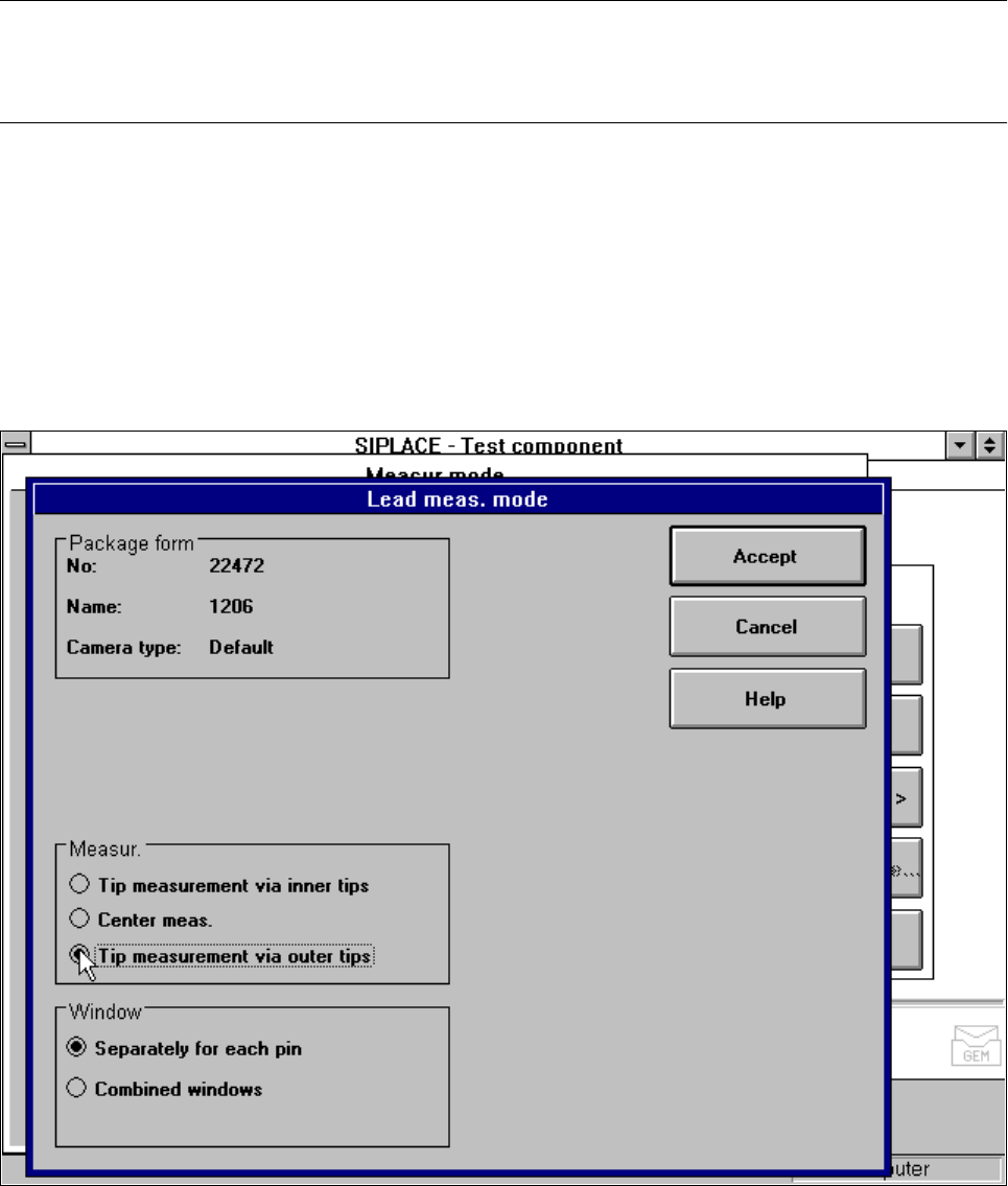
5.6.4.19 ‘Lead’ measuring mode
Click on the ‘Setting’ field in the ‘Lead’ measuring mode to call up the
Lead measuring mode
menu.
Fig. 5.6.40
Measuring mode
option,
Lead measuring mode
menu
This menu is used to
– specify the lead measuring method.
– to select the windows separately for each lead or a combined window for every lead to be measured.
Measurement
If the inner lead tips are mapped better than the outer tips, for example if a shiny lead is bent upwards slightly,
you can select one of the following options:
5 Vision Functions SIPLACE 80S-20/F4/F5 User Manual
5.6 Test Component 05/99 Issue from Software Version SR.405.xx
5 - 124 Line engineer
– measuring the tips via the inner tips of the leads, for bases, for example
– center of the lead, center measurement, for PLCC, SOJ, for example
– measuring the tips via the outer tips of the leads, for QFP, SOT, SO, for example
Windows
–
Separately for each lead
Here you define the window in the primary direction (dark blue) and secondary direction (light blue) for
measuring each standard lead for irregular components and special components.
–
Combined window
Used to define a common window for all the leads. This applies to four-sided, symmetrical components
only.
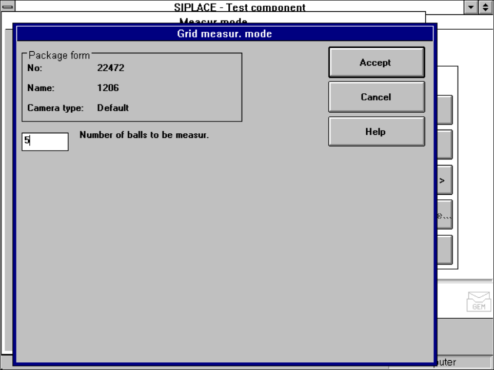
5.6.4.20 ‘Grid’ measuring mode
Click on the ‘Setting’ field in the ‘Grid’ measuring mode to call up the
Grid measuring mode
menu.
Fig. 5.6.41
Measuring mode
option,
Grid measuring mode
menu
In this menu, enter the number of balls to be measured at each corner:
– 3 for single measurement
– 5 for multiple measurement